6-12 Electrical Data Rexroth IndraDrive C
DOK-INDRV*-HCS02.1****-PR02-EN-P
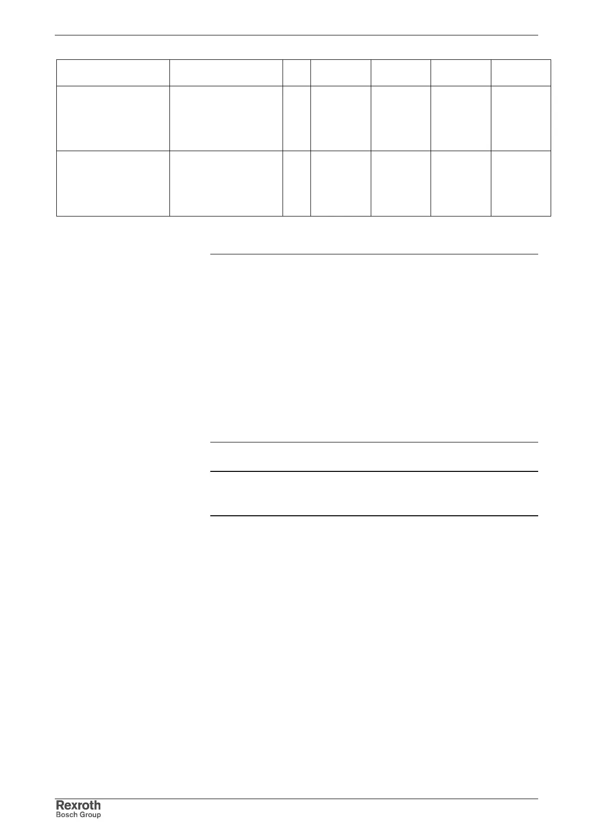
Designation Symbol Unit HCS02.1E-
W0012
HCS02.1E-
W0028
HCS02.1E-
W0054
HCS02.1E-
W0070
maximum output current
t=60s; T=10min; K=1.2
I
out_peak_5 (4 kHz)
I
out_peak_5 (8 kHz)
I
out_peak_5 (12 kHz)
I
out_peak_5 (16 kHz)
A
eff
4.9
4.9
4.2
2.9
13.4
9.7
5.4
4.7
22.9
22.2
14.3
11.6
30.9
22.9
15.1
11.2
base load current
available at maximum
current
t=60s; T=10min; K=1.2
I
out_base_5 (4 kHz)
I
out_base_5 (8 kHz)
I
out_base_5 (12 kHz)
I
out_base_5 (16 kHz)
A
eff
4.1
4.1
3.5
2.4
11.2
8.1
4.5
3.9
19.1
18.5
12.0
9.6
25.8
19.1
12.6
9.3
Fig. 6-12: Data load profiles – inverter
Note: The load profiles are characterized by their time flow and the
corresponding currents and are representing the output
current capacity. These profiles are limited by the drive
controller via the thermal effect of the output current. When
the current limitation is triggered, it is therefore necessary to
compare the actual load with the above data and, if necessary,
• reduce the load with I
out_ max
or
• reduce the pulse time or
• increase the cycle time or
• reduce the switching frequency f
s
or
• use a device with higher type current
(See also Functional Description and Troubleshooting Guide
of the firmware.)
Note: The load profiles are available if particularly the maximum
current at switching frequencies of 8, 12 and 16 kHz is
externally (e.g. by the NC) limited to the indicated values.
 Loading...


