Rexroth IndraDrive C Electrical Data 6-9
DOK-INDRV*-HCS02.1****-PR02-EN-P
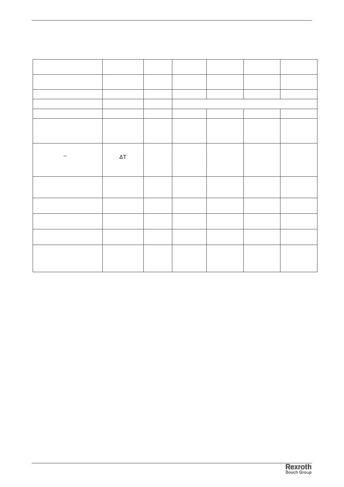
6.4 Power Section – Braking Resistor
Designation Symbol Unit HCS02.1E-
W0012
HCS02.1E-
W0028
HCS02.1E-
W0054
HCS02.1E-
W0070
nominal braking resistor
(internal)
R
DC(Bleeder)
Ohm 180 72 40 28
max. regenerative power W
R,MAX
kWs 1 5 9 13
braking resistor threshold R
DC (R_DC On)
V see Functional Description of firmware
cooling of braking resistor forced forced forced forced
braking resistor peak power
at U
DC
= 850 V
(allowed load cycle)
P
BS
kW 4
(0.25s ON;
20s OFF)
10
(0.5s ON; 33s
OFF)
18
(0.5s ON; 26s
OFF)
25
(0.5s ON; 25s
OFF)
braking resistor continuous
power, at Ta<40 °C
under max. temperature
range with distance from
top side of housing
1)
P
BD
∆
T
d
KW
K
mm
0.05
12
80
0.15
40
80
0.35
40
80
0.5
50
80
balancing factor for P
BD
(for parallel operation with
common DC bus)
- 0.8 0.8 0.8
operation external braking
resistor (optional)
-- -- allowed allowed
min. resistance of external
braking resistor
R
DC(Bleeder)
Ohm----4028
allowed continuous power
of external braking resistor
kW -- -- 3.8 5.5
ext. braking resistor peak
power
at U
DC
= 850 V
(allowed load cycle)
2)
P
BS
kW -- -- 18
(5.5s ON; 26s
OFF)
25
(5.5s ON; 25s
OFF)
1) see also section Temperatures Above the Top of the Device on page
5-5
2) take energy absorption capacity of external braking resistor into
account
Fig. 6-10: Data power section – braking resistor