EasyManuals Logo

REXROTH IndraDrive C Series User Manual

REXROTH IndraDrive C Series
98 pages
To Next Page IconTo Next Page
To Previous Page IconTo Previous Page
Page #10 background imageLoading...
Page #10 background image
1-4 Introduction Rexroth IndraDrive C
DOK-INDRV*-HCS02.1****-PR02-EN-P
Control Section
The control section is a separate section which is inserted into the power
section. The drive controller is supplied ex works complete with control
section
The control section must only be replaced by a trained person.
The contacts X31/1 and X31/2 are connected to the control section as Bb
contacts.
Note: The control sections are described in a separate
documentation (see page 1-2).
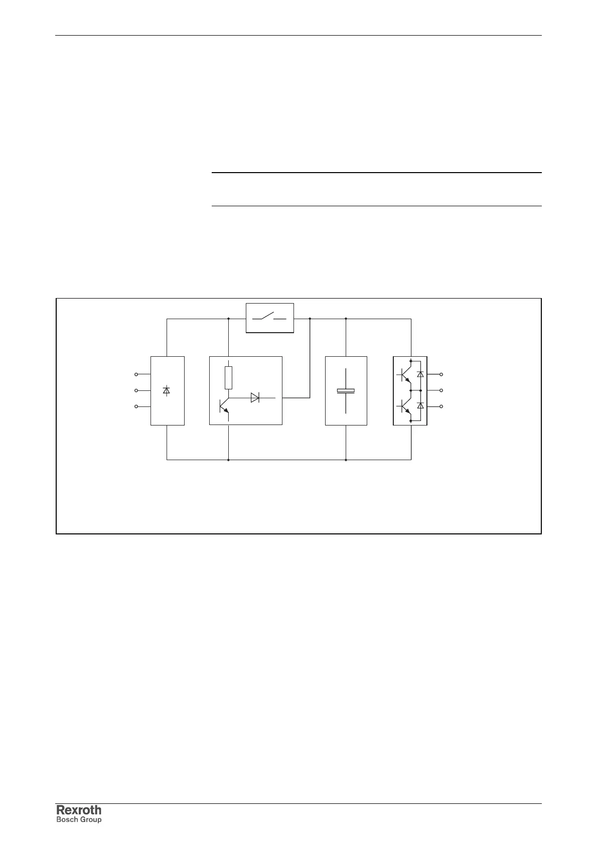
1.3 Drive Controllers - Block Diagram
HCS02.1E-W0012-NNNN
line input with
bridge circuit
rectifier
DC bus
capacitance
converter
bridge circuit
with output to
the motor
braking resistor
circuit
charging
current limit
C
ZW
R
Softstart
R
B
hcs_block_12n.FH7
A1
A2
A3
L1
L2
L3
Fig. 1-3: HCS02.1E-W0012-NNNN - Block diagram

Table of Contents

Questions and Answers:

Question and Answer IconNeed help?

Do you have a question about the REXROTH IndraDrive C Series and is the answer not in the manual?

REXROTH IndraDrive C Series Specifications

General IconGeneral
Protection ClassIP20
Communication InterfacesEtherCAT, PROFIBUS, PROFINET, CANopen
Feedback SystemsIncremental Encoders, Absolute Encoders, Resolver
Ambient Temperature0°C to 45°C
Cooling MethodNatural convection or forced air
Relative Humidity5% to 85% (non-condensing)
Control ModesTorque, position

Related product manuals