Rexroth IndraDrive C Electrical Data 6-19
DOK-INDRV*-HCS02.1****-PR02-EN-P
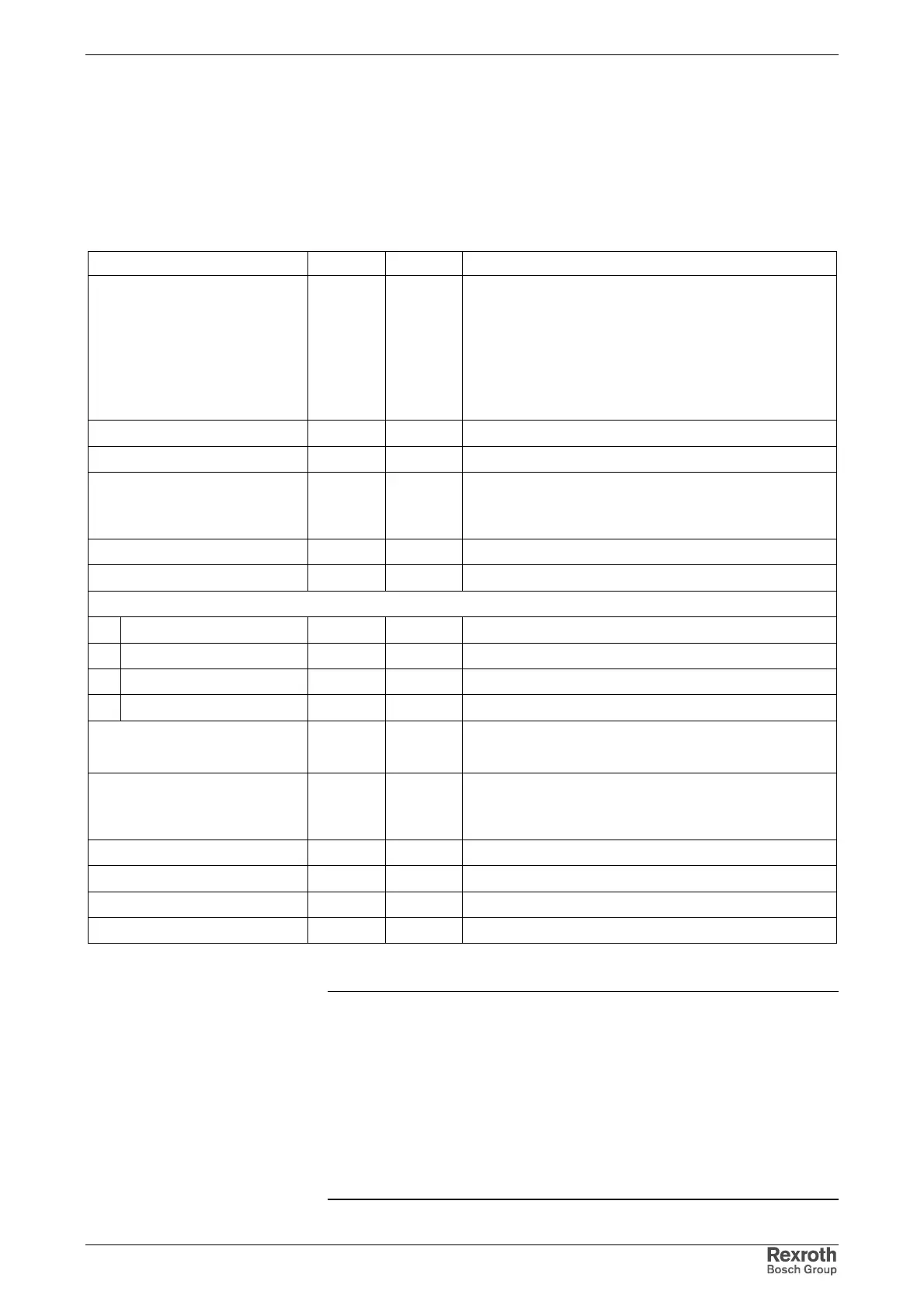
Devices with Internal Control Voltage Supply Generation from DC bus
(HCS02.1E-W00xx-NNNV)
The internally generated control voltage is used for stand-alone supply of
the drive controller or buffering in case the external 24V supply fails. It is
not used for supplying motor holding brakes.
(Information at ambient temperature of 25 °C)
Designation Symbol Unit Value
control voltage U
N3
V
• 24 ±20%
(when no motor holding brake is used)
• If motor holding brakes are to be supplied, observe
the data of the motor documentation. The following
values are normally sufficient:
24 ±5% with motor cable length <50 m
26 ±5%
with motor cable length >50 m
max. ripple content w - mustn't exceed the control voltage range
max. allowed overvoltage U
N3max
V 33 (max. 1 ms)
max. charging current I
EIN3
A2.8
plus charging current of control section (see Project
Planning Manual IndraDrive Control Sections)
max. pulse duration of I
EIN3
t
EIN3Lade
ms 15
max. input capacity C
N3
mF 1.2 * 0.47
power consumption*:
HCS02.1E-W0012 P
N3
W12
HCS02.1E-W0028 P
N3
W14
HCS02.1E-W0054 P
N3
W23
HCS02.1E-W0070 P
N3
W23
internally generated control
voltage
U
N3
V
24 ±10%
(not used for supplying the motor holding brake)
output power
for required power of control
section CS* and power section
W70
power dissipation W 25
short-circuit strength present
overload withstand capability present
overtemperature protection present
Fig. 6-19: Control voltage -***V
Note: Overvoltages of more than 33 V have to be derived by
measures in the electrical equipment of the machine or
installation. This includes:
• 24-Volt mains sections that reduce incoming overvoltages
to the allowed value.
• Overvoltage limiters at the control cabinet input that limit
existing overvoltages to the allowed value. This also
applies to long 24-Volt lines that have been laid in parallel
with power and mains cables and can absorb overvoltages
caused by inductive or capacitive coupling.

 Loading...


