EasyManuals Logo

REXROTH IndraDrive C Series User Manual

REXROTH IndraDrive C Series
98 pages
To Next Page IconTo Next Page
To Previous Page IconTo Previous Page
Page #60 background imageLoading...
Page #60 background image
6-20 Electrical Data Rexroth IndraDrive C
DOK-INDRV*-HCS02.1****-PR02-EN-P
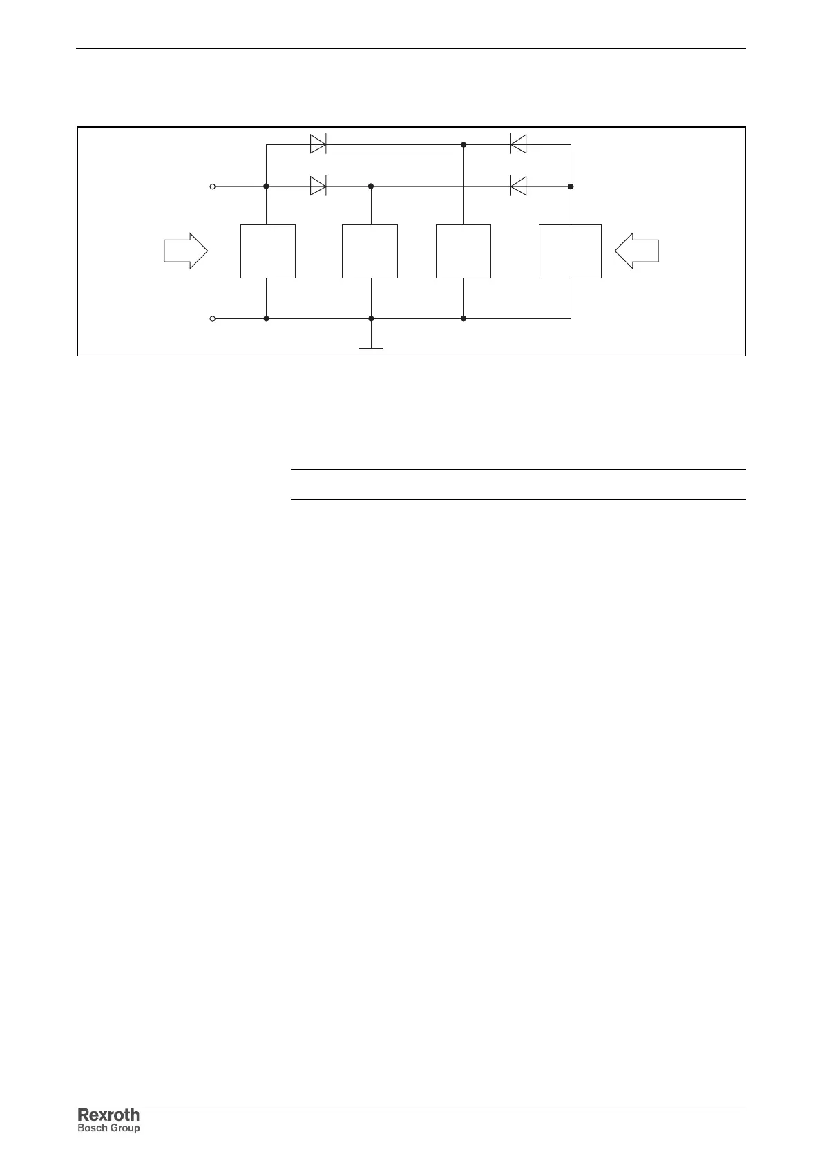
Block diagram of control voltage generation from the DC bus:
24 V
hcs_block_steuerspg.fh7
Br LT ST
int.
SMPS
(optional)
ZK
Br: brake circuit
LT: power section
ST: control section
int. SMPS: internal switching-mode power supply
ZK: DC bus
Fig. 6-20: Block diagram of internal control voltage generation
Note: The external 24V supply takes place via connection X13.

Table of Contents

Questions and Answers:

Question and Answer IconNeed help?

Do you have a question about the REXROTH IndraDrive C Series and is the answer not in the manual?

REXROTH IndraDrive C Series Specifications

General IconGeneral
Protection ClassIP20
Communication InterfacesEtherCAT, PROFIBUS, PROFINET, CANopen
Feedback SystemsIncremental Encoders, Absolute Encoders, Resolver
Ambient Temperature0°C to 45°C
Cooling MethodNatural convection or forced air
Relative Humidity5% to 85% (non-condensing)
Control ModesTorque, position

Related product manuals