EasyManuals Logo

REXROTH IndraDrive C Series User Manual

REXROTH IndraDrive C Series
98 pages
To Next Page IconTo Next Page
To Previous Page IconTo Previous Page
Page #38 background imageLoading...
Page #38 background image
5-6 Mechanical Data Rexroth IndraDrive C
DOK-INDRV*-HCS02.1****-PR02-EN-P
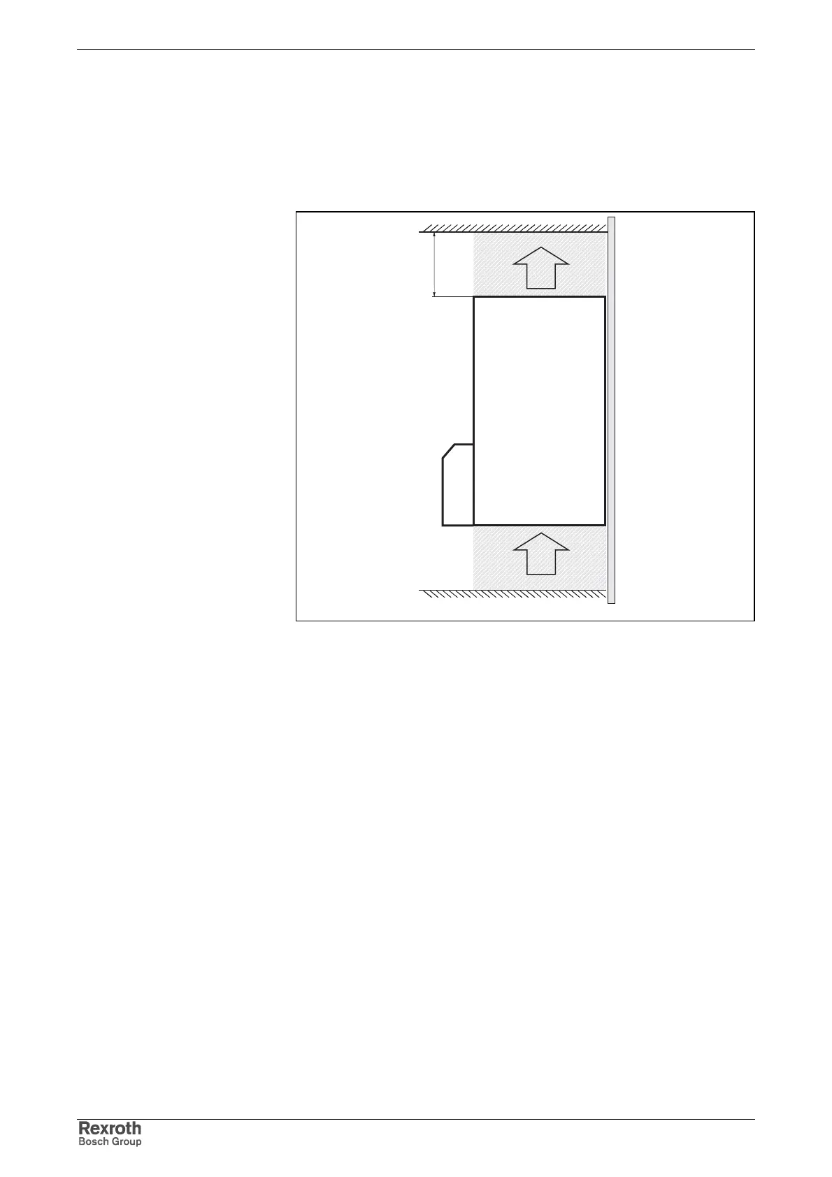
Outlet Temperatures in Normal Operation
The diagrams below (see next page) show the temperature rise of the air
from air intake at the bottom of the device to air outlet at the top of the
device, depending on the average continuous power at the breaking
resistor. The values "d" are representing different distances from the top
of the device (see following figure):
kuehlluft.FH7
d
A
B
C
A: air inlet
B: air outlet
C: control cabinet mounting plate
d: distance from the top of the device (see also following diagrams)
Fig. 5-6: Air inlet and outlet of drive controller

Table of Contents

Questions and Answers:

Question and Answer IconNeed help?

Do you have a question about the REXROTH IndraDrive C Series and is the answer not in the manual?

REXROTH IndraDrive C Series Specifications

General IconGeneral
Protection ClassIP20
Communication InterfacesEtherCAT, PROFIBUS, PROFINET, CANopen
Feedback SystemsIncremental Encoders, Absolute Encoders, Resolver
Ambient Temperature0°C to 45°C
Cooling MethodNatural convection or forced air
Relative Humidity5% to 85% (non-condensing)
Control ModesTorque, position

Related product manuals