User Manual Bearing System RT-300
Issue: 2017/06/27 [Rev 1.04.c] Page 17 of 79 12-9-1-0013-9-2-0001-3-1-60
5 Display and Operating
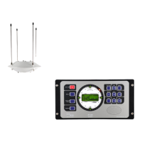
All display and operating elements are situated on the front of the Display-Control-Unit (DCU).
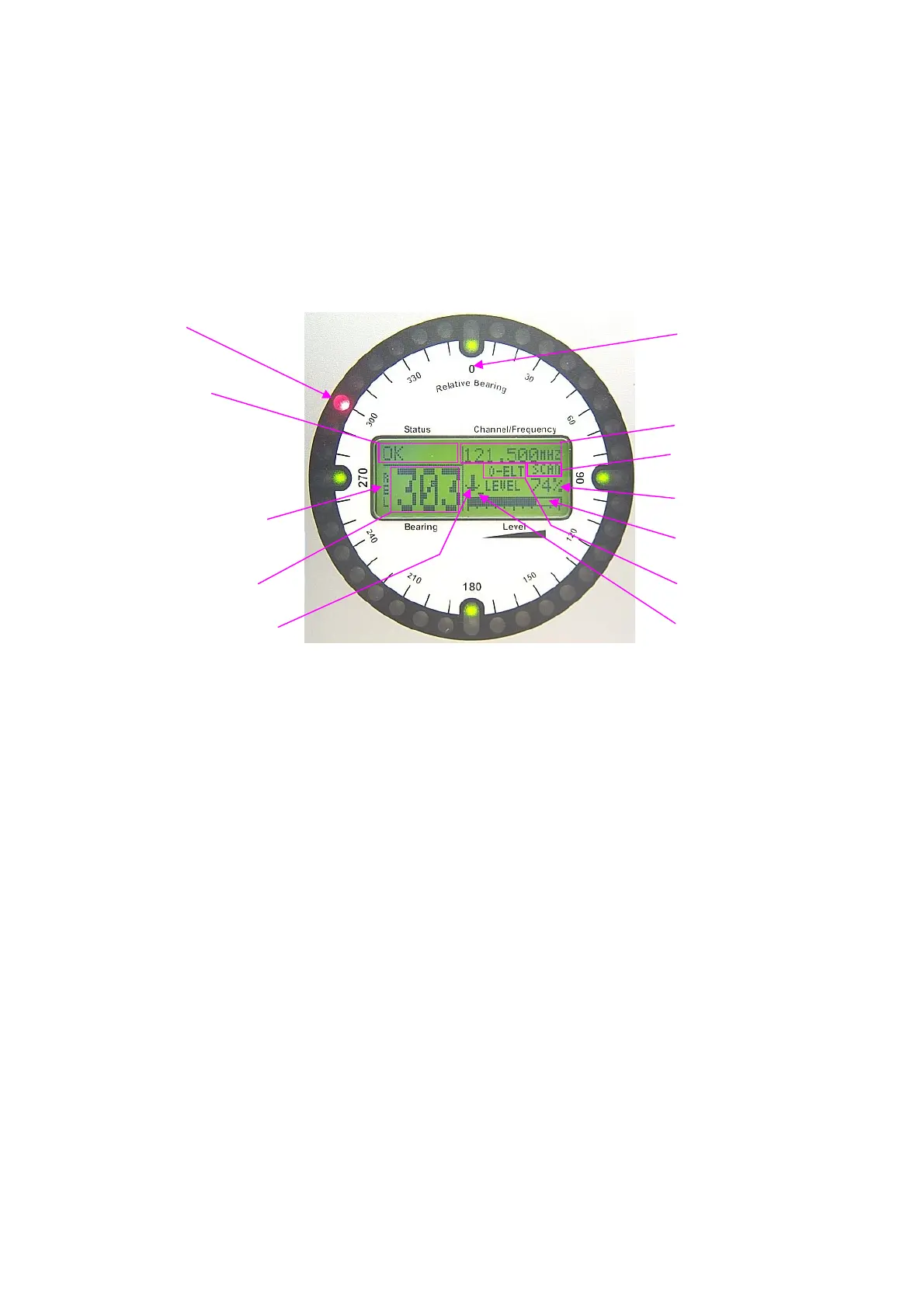
5.1 Display
LED circle general lighting
status display
display
frequency/channel
scan display
level digital
direction of reference
level analog
digital bearing value selective squelch
status of alarm-contact squelch-level
Fig. 7: Display
5.1.1 LED-Circle
Corresponding to a resolution of 10°, the LED-circle is made of 36 red LED’s.
The reference direction of the display is always relative to the bearing antenna and therefore to
the longitudinal axle of the vessel. The preset offset-value will be considered in the display.
Brightness of the display may be adjusted in submenu LIGHT - DIM CIRCLE.
Receiving a signal, the bearing value will be displayed with the corresponding LED. If the signal
isn`t received anymore for a certain time, the last bearing value will be displayed with the
corresponding LED flashing. This time may be adjusted in the submenu SETUP -BEARING -
LAST TIME.
5.1.2 General Lighting
There are 4 green LEDs within the LED-circle as an orientating aid. They are placed in the
directions north, east, south and west.
The brightness of these green and red LEDs may be adjusted in submenu LIGHT - DIM
CIRCLE.