User Manual Bearing System RT-300
Issue: 2017/06/27 [Rev 1.04.c] Page 36 of 79 12-9-1-0013-9-2-0001-3-1-60
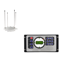
6.2.1.2.2 Display Bearing Parameters: VIEW BEARING SETUP
In the submenu BEARING select display function VIEW BEARING
SETUP, see Fig. 40.
The important bearing adjustments are shown here.
Designation Meaning Range See
chapter.
AVERAGING-
LEVEL
Depth of averaging store 1 ... 9 6.2.1.5.1.1
COMPENSATION drag error compensation by compass data ON / OFF 6.2.1.5.1.2
MOUNTING Antenna mounting
normal = mast upright
inverse = mast downright
normal, inverse 6.2.1.5.1.3
OFFSET Offset value to be added to bearing value,
e.g. in order to compensate mounting
errors.
0 – 360° 6.2.1.5.1.4
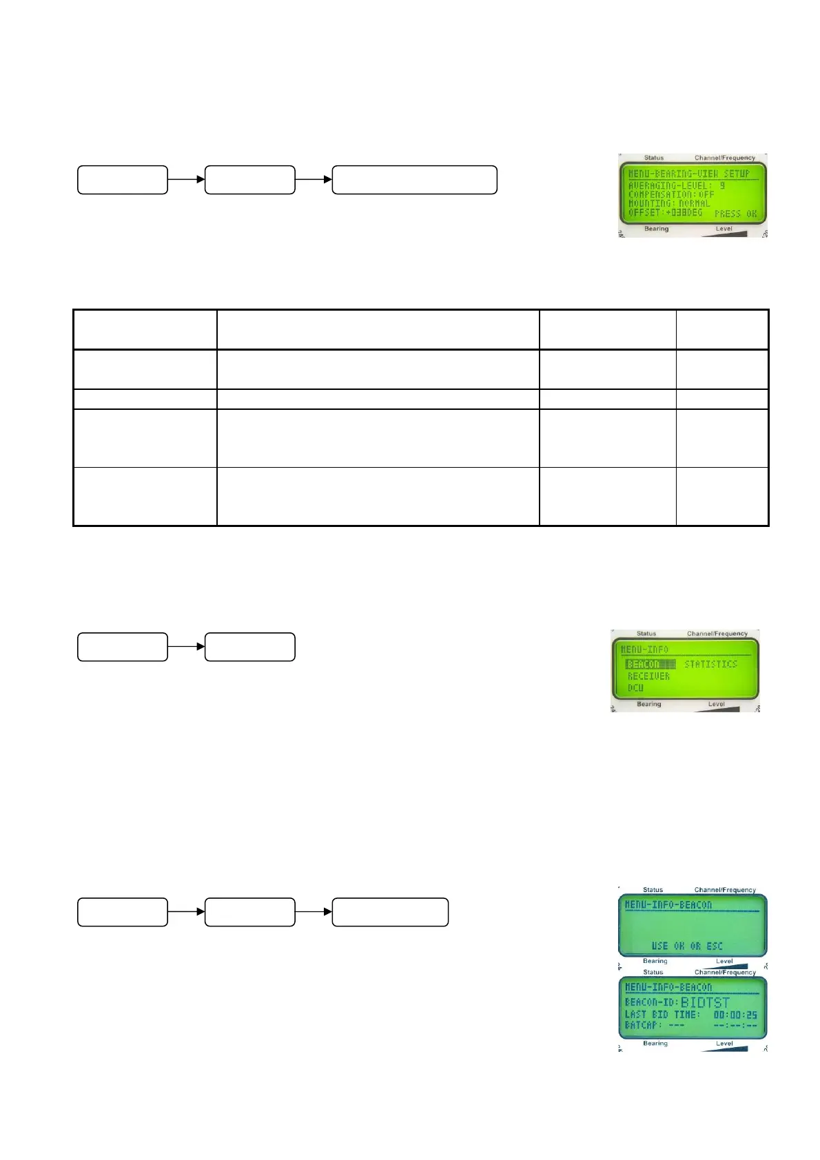
6.2.1.3 Menu: INFO
Following information can be displayed in the submenu INFO:
BEACON: Receiver identification
RECEIVER: Receiver data
DCU: Data of the Display Control Unit (DCU)
STATISTICS: Operating data of the system
6.2.1.3.1 INFO Beacon
In the submenu INFO select display function BEACON. The display
appears as shown in Fig. 42.
If the BeaconID is received, the BeaconID can be displayed in the
submenu INFO - BEACON.
Fig. 40
Fig. 41
Fig. 42
M
n
BEARING VIEW BEARING SETUP
M
n
INFO
Menu
INFO
BEACON