User Manual Bearing System RT-300
Issue: 2017/06/27 [Rev 1.04.c] Page 73 of 79 12-9-1-0013-9-2-0001-3-1-60
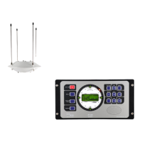
7.4.4 Fixing the Antenna
- Connect antenna cable and antenna, tighten check-screws.
- Put antenna to the mast-flange. Take care, that the o-ring of the antenna flange is fitting
firmly into its groove.
- Tighten slightly the compression nut (threaded flange).
- Align antenna, the arrow-marked dipole pointing exactly in the longitudinal axis of the vehicle.
- Tighten firmly screw joint.
- If using the 6-holed flange, mount antenna with the arrow pointing to the vehicles direction.
- For stationary use, mount antenna with the arrow pointing to the north.
7.4.5 Aligning Antenna for Mobile Use
Before putting into operation the bearing system, the bearing antenna is to be aligned exactly.
For vessels and land vehicles the reference direction is the longitudinal axis of the vehicle. The
bearing antenna should be aligned in a way, that the arrow-marked pair of beams is pointing
parallel to the longitudinal axis to the bow respectively to the front of the vehicle.
By means of a transmitter, the correct alignment can be verified.
In case of an inevitable, unfavourable antenna position, antenna axis and vehicle axis may not
coincide (offset) due to reflexions.
7.4.6 Aligning Antenna for Stationary Use
For stationary use the reference direction of the antenna is magnetic north (QDR) or geographic
north (QTE).
Aligning for reference direction magnetic north (QDR, from direction finder to transmitter):
a) A transmitter is to be put up in a distance of at least 100 m from the bearing antenna.
b) Determine the direction to the bearing antenna by means of a compass.
c) Add or subtract to compass value 180°, thus obtaining the nominal value.
d) Switch on transmitter, transmitting continuously.
e) Align antenna in a way, that the display is indicating the nominal value.
f) Tighten screw-joint of antenna.
For verifying purposes the adjustment has to be checked for different directions of transmission.
In case of (untolerable) deviations, change position of antenna.
Aligning for reference direction QDM (magnetic course from transmitter to direction finder):
To be done as described in "Aligning for reference direction magnetic north QDR ", only the
nominal value has to correspond to the determined compass value.
ATTENTION
Touching the antenna during rotation will considerably distorting the bearing
result. Before reading the bearing results at the DCU, take care that there are no
persons in the vicinity of the antenna.