User Manual Bearing System RT-300
Issue: 2017/06/27 [Rev 1.04.c] Page 66 of 79 12-9-1-0013-9-2-0001-3-1-60
31245
6789
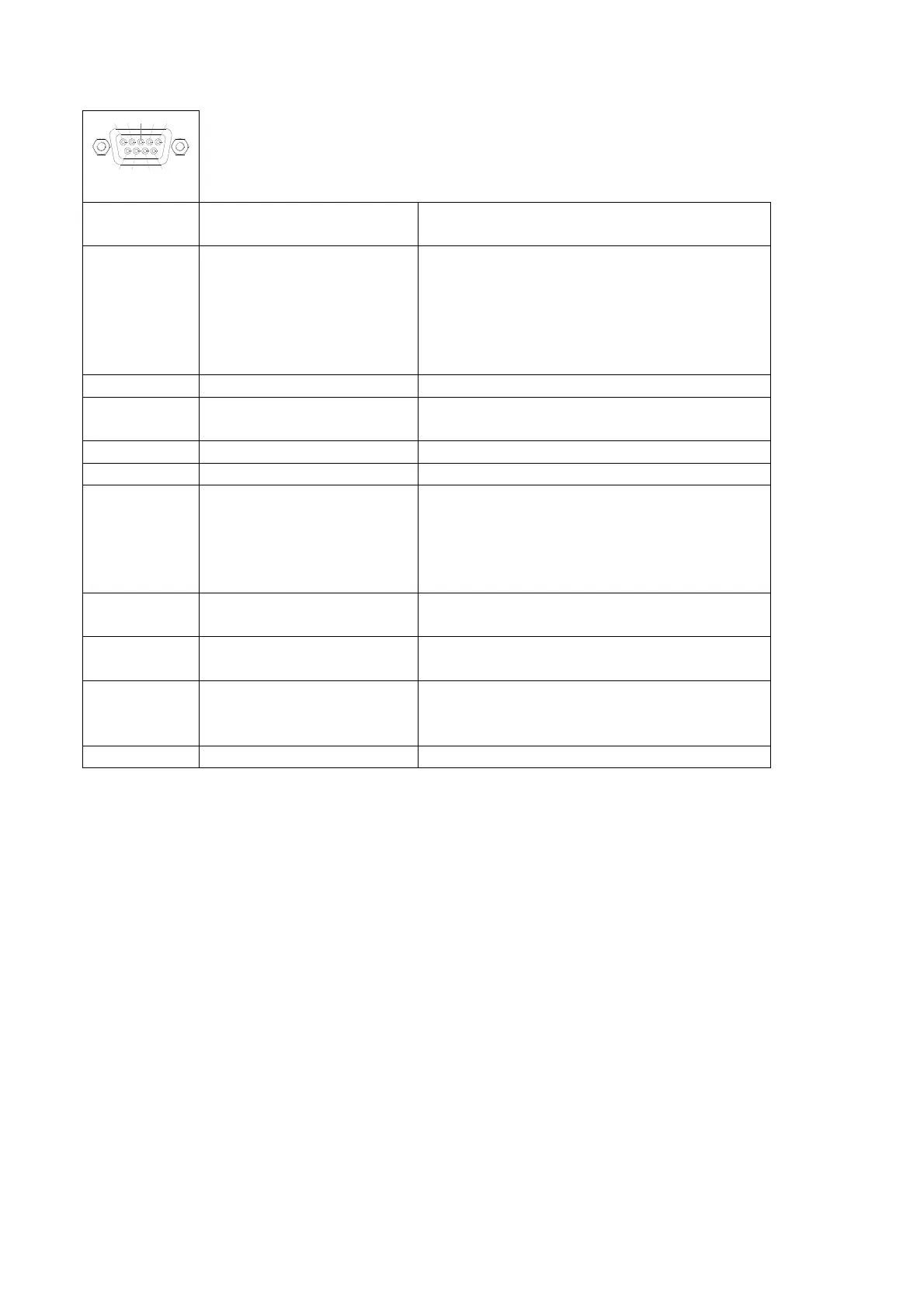
D-Sub-socket
Contact
(PIN)
Signal name Signal
1 RS485TRX/RS422TX-B Depending on adjustment, see
6.2.1.5.3.1
Selection:
RS485 RS-485 TRX-line
NMEA RS-422 TX-B-line
RS232 RS-232 TX-B-line
2 RS232TX TX-line RS-232-interface (always active)
3 RS232RX RX-line RS-232-interface
(activating see 6.2.1.5.3.1)
4 RS422RX-SHIELD RS-422 receiving line GND
5 GND Ground
6 RS485TRX/RS422TX-A Depending on adjustment see 6.2.1.5.3.1
Selection:
RS485 RS-485 TRX-line
NMEA RS-422 TX-B-line
RS232 RS-232 TX-B-line
7 RS422RX-A RS-422 receiving line anode
activation see 6.2.1.5.3.1
8 RS422RX-B RS-422 receiving line cathode
activation see 6.2.1.5.3.1
9 +5V-OUT Voltage supply +5V DC
(voltage supply for interface modules)
Current output: max. 200 mA
Shield GND Ground
6.4.3.1 RS-232-Interface
For interface functions see documentation “RT-300 NMEA Serial Communication & Remote
Control”
6.4.3.2 RS-485-Interface
For interface functions see documentation “RT-300 NMEA Serial Communication & Remote
Control”
6.4.3.3 NMEA (RS-422) Interface
For interface functions see documentation “RT-300 NMEA Serial Communication & Remote
Control”