User Manual Bearing System RT-300
Issue: 2017/06/27 [Rev 1.04.c] Page 63 of 79 12-9-1-0013-9-2-0001-3-1-60
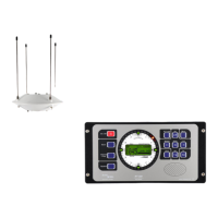
Pin wiring:
31245
6789
D-Sub-socket
Contact
(PIN)
Signal Name Signal
1 ANT-EAST control signal east
2 ANT-WEST control signal west
3 RS485/A data signal
4 RS485/B data signal
5 12..28V voltage supply
6 ANT-SOUTH control signal south
7 ANT-NORTH control signal north
8 NF audio signal
9 PHI bearing signal
Shield GND ground
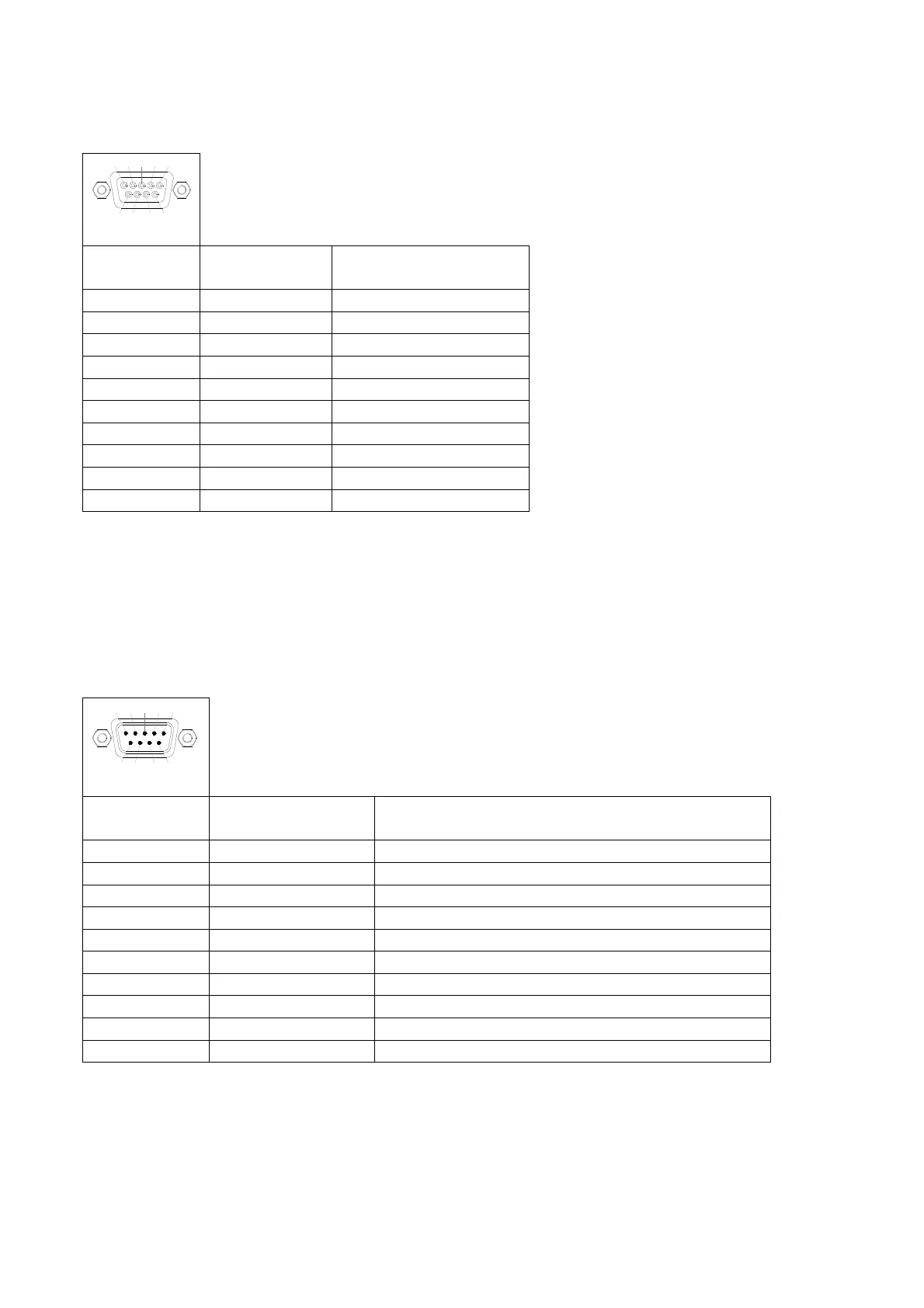
6.4.2 Power Connector
The power supply is connected to the Power Connector (Fig. 2 ). Additionally this connector
contains contacts for the external speaker, alarm relay and input for the SBS-function (self-
bearing suppression).
312 45
67 89
D-Sub-socket
Contact
(PIN)
Signal Name Signal
1 GND internal and housing ground,
2 NF-OUT-B audio exit for external speaker
3 RELAY-B alarm contact
4 RELAY-A alarm contact
5 U-IN-GND negative voltage supply
6 ANALOG-TEST not connected
7 NF-OUT-A audio exit for external speaker
8 EXT-INPUT input for SBS-function
9 U_IN_12..28V positive voltage supply (12 ..28 V)
Shield GND housing ground, frame