User Manual Bearing System RT-300
Issue: 2017/06/27 [Rev 1.04.c] Page 70 of 79 12-9-1-0013-9-2-0001-3-1-60
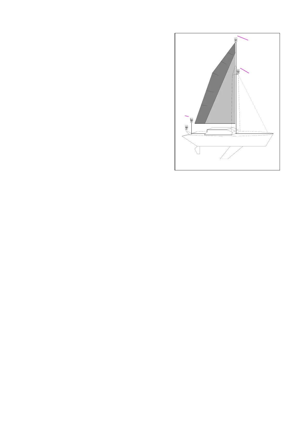
Example Fig. 100:
Position : bearing optimal
Position : bearing good
Position : bearing sufficient
Position : bearing sufficient
7.3 Completing Antenna Cable
The delivery contains an antenna cable of 10m length. First of all this cable is intended for
testing operation of the system. Usually a special cable connection has to be put together for
the final assembly. The content of delivery contains the required plugs and mounting material.
7.3.1 Type of Cable
The connecting cable antenna DCU has to have following features:
- Cable length up to 50 m:
Cross-sectional area: min. AWG 24 (0,23mm²),
Number of wires: 9-poled (or more) + shield
Type of cable: control cable; twisted wires not required. The type of cable in detail is
depending on local requirements (fire protection, oil resistance, heat…).
If there are no special requirements, a cable of type LiYCY10X0,25mm
2
may be used.
DC resistance of the shield: ≤ 15.7 Ω / km
- Cable length up to 100 m:
Cross-sectional area: min. AWG 22 (0,38 mm²),
Number of wire pairs: 12-poled twisted in pairs (or more) + shield
DC resistance of the shield: ≤ 6,4 Ω / km
Type of cable: control cable; wires twisted in pairs. The type of cable in detail is
depending on local requirements (fire protection, oil resistance, heat…).
If there are no special requirements, a cable of type LifYCY6x2x0,50
mm
2
(METROFUNK KABEL-UNION) may be used.
7.3.2 Connecting Pattern of Antenna Cable:
Fig. 100