User Manual Bearing System RT-300
Issue: 2017/06/27 [Rev 1.04.c] Page 75 of 79 12-9-1-0013-9-2-0001-3-1-60
7.5 Configuring Setup
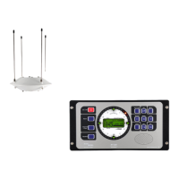
Once antenna and DCU connected to the power supply, the bearing system will work already.
The factory defaults are set (see 6.2.1.5.6) in a way, that all standard functions are activated.
The bearing system is offering a great number of functions, different settings and external
devices may be connected. In order to be able to use these features, some adjustments have to
be made prior putting into operation the system. The following chapter is to support you for this
work.
Procedure:
Pos Menu Action Default See
chapter.
Remarks
01 Light Adjusting brightness of LCD 100% 6.2.1.1.1
02 Brightness of keyboard 50% 6.2.1.1.2
03 Brightness LED-circle 100% 6.2.1.1.3
04 Bearing Select reference direction for digital
bearing value display
- REL (relative bearing )
- MAG (magnetic bearing
reference direction magnetic
north )
- TRU (true bearing reference
direction geographic north)
REL 6.2.1.2.1 For reference directions MAG
and TRU the source of
compass data has to be
defined in menu COMPASS.
If using an external compass,
in menu SERIAL the interface
has to be defined.
05 Sounds Adjusting keyboard volume
- BEEP VOLUME
50% 6.2.1.4.1 Adjust volume audible, but not
disturbing.
06 Adjusting volume alarm signal
- ALARM VOLUME
100% 6.2.1.4.2
07 Setup
Bearing
Bearing value averaging memory
- AVERAGE
5 6.2.1.5.1.1 A higher value is only useful,
if drag error compensation is
activated (drag error will
increase). Smaller values
cause nervous display.
08 Adjusting source for heading
compensation.
- OFF: no heading
compensation
- TRUE: source of heading
compensation has
reference direction true
north
- MAG: heading compensations
has reference direction
magnetic north
- INT: heading compensation
by internal compass
OFF 6.2.1.5.1.2 Only one source can be
selected, which is actually
available. If selecting MAG or
TRUE a corresponding
compass signal has to be
connected. If selecting INT,
the internal compass module
(optimal) has to be integrated.
If there is an external
compass connected, it should
be used as a source.
09 Selecting mounting direction of
antenna.
- NORM (normal mounting)
- INVERS (mounting upright
down)
NORM 6.2.1.5.1.3
10 Adjusting correcting value
- Offset
0° 6.2.1.5.1.4 With the correcting value
constant bearing errors may
be compensated, e.g. caused
by misalignment.
11 Extended display 10 sec. 6.2.1.5.1.5 Adjusting only recommended,