User Manual Bearing System RT-300
Issue: 2017/06/27 [Rev 1.04.c] Page 67 of 79 12-9-1-0013-9-2-0001-3-1-60
7 Installation and Putting into Operation
7.1 Installation of Display-Control-Unit DCU
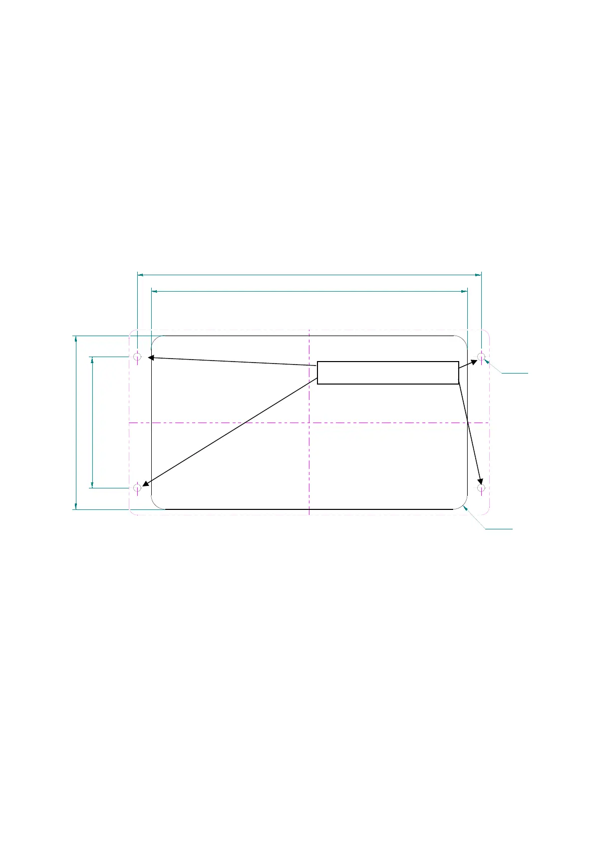
7.1.1 DCU Installing Cut-Out
The DCU is to be installed in an instrument panel in a suitable position. Therefore, an installing
cut-out, as shown in Fig. 98, has to be set.
NOTE
Choose installing position in a way, that the DCU is not exposed to excessive heat.
In order to achieve good reading, on vessels the installing position of the DCU should be
situated within the range of view of the control desk.
Installing
Make sure, that there are no endangered elements (e.g. wiring, gas- or water pipes) within
the range of the installing cut-out.
Cut out attached mounting template, transfer the 4 fixing holes and the installing cut-out to
the mounting surface.
Drill the four 4.5 mm holes for the fixing screws or tap four M4-threads into the mounting
surface, in order to achieve comfortable installing from the front.
Cut out the installing cut-out of the mounting surface.
193
210
106
80
R8.5
ø4.5
Fig. 98
alternative tapping M4