Appendix: Accessories
1. Carriage unit 2. Procedure 3. Waste ink tank 4. Ink cartridges
5. Guide rod fastening tool (x2;
right side of photo), guide rod
removal tool (x1; left side of photo)
6. Main scan encoder
sheet
Notice:
Please be informed of the following as this kit is commonly used with Japanese models.
• Both English and Japanese procedure are bundled.
• Ink cartridges are are labeled in Japanese but can be used in all models.
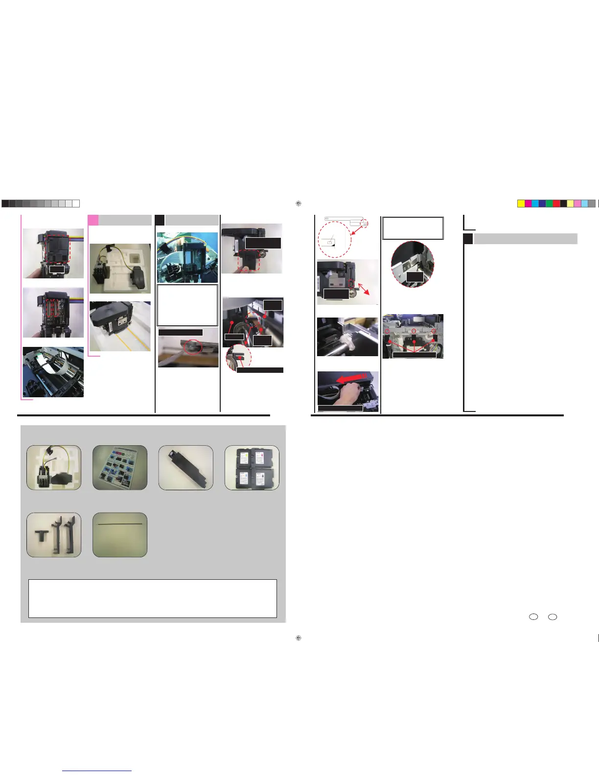
Attach new carriage
2. Attach the carriage’s rear cover.
5. Remove the jigs. (See Step C-2)
4. Re-insert the guide rod into the
carriage. (See Step C-4)
5
3. Secure the FFC to the jigs.
1. Attach the 2 FFCs.
6. Attach the belt.
Lower
belt
Upper
belt
Carriage
Slide the belt into the gap
3. Remove the humidity retention cap.
Humidity retention
cap
CAUTION:
䊶Be careful not to fold them.
䊶One FFC is longer than the
other. Make sure to attach the
longer FFC in the right position
shown in the photo in Step D-2
(and shorter FFC in the left
position).
Cover
1. Remove the cover from the rear
side of the carriage unit.
Do not fold the FFCs
F
Adjustment after replacement
2. Enter SP mode.
4. Install the starter ink cartridges.
5. Install the ink collector unit.
8. Adjust the print head position.
[Menu]ą[Maintenance]ą[Head Position]*1
9. Adjust the registration.
[Menu]ą[Maintenance]ą[Registration]*2
10. Adjust the paper feed.
[Menu]ą[Maintenance]ą[Adj. Paper Feed]
11. Print out the color demo page.
[Menu]ą[List/Test Print]ą[Color Demo Page]
12. Print out the engine summary (SP 5200).
13. Replace the ink collector unit and ink cartridges with the ones
the customer was originally using.
6
14. Attach the guide lock. See Step C-3-3.
15. Attach the ink supply unit See Step B-1.
16. Attach the front cover. See Step A-7.
17. Attach the operation panel. See Step A-6.
18. Attach the right cover.See Step A-4.
10. Attach the cam (screw x1). See Step C-3-5.
11. Attach the spring. See Step C-3-4.
12. Attach the linkage. See Step C-3-2.
Carriage attachment completed.
1. Open the ink cartridge cover before you turn on
the machine main power. Otherwise the machine
will perform auto maintenance and consume a large
amount of ink.
3. Execute SP5101.
(Some values related to print head will be reset)
6. Close the ink cartridge cover.
IMPORTANT: Ink initialization will start. During the initialization, do not
open any covers, or turn off the power. The entire process will take
about seven minutes.
IMPORTANT: Check to see if the nozzle is clogged, and If it is, perform
print head cleaning.
7. Print out the nozzle check pattern.
[Menu]ą[Maintenance]ą[Nozzle check]
8. Hook the right end of the
encoder sheet first, then hook the
left end.
Right side
Left
side
Plate
spring
9. Clean the strip with alcohol by
wiping the surface from right to
left.
CAUTION:
If you wipe the surface from the
left side, this may damage the
plate spring.
Clean from right side
Order to fasten screws
13. Attach the stay plate.
20. Attach the ink cartridge cover. See Step A-5.
21. Attach the output tray and paper
tray. See Step A-1 and 2.
19. Attach the upper/inner cover. See Step A-3.
22. Reset the envelope lever to standard position.See Step B-2.
Right
Hole
Marking
Left
Right
Through this
opening
Left
*1: 䇸Standard䇹-䇸High Speed䇹-䇸High Quality䇹䇭䇭䇭*2: Only “Tray 1-Plain Paper”
 Loading...