Chapter 1 Quick Start RIGOL
MSO4000/DS4000 User’s Guide 1-31
2. Analog Channel Label and Waveform
Different channels are marked in different colors. The channel label and
waveform are marked in the same color as the analog channel.
3. Digital Channel Label and Waveform
The logic high levels of the digital channel waveforms are displayed in blue; the
logic low levels are displayed in green which complies with the color of the
digital channel label and the edges are displayed in white. The label and
waveform of the digital channel currently selected are both displayed in red.
Note: Only applicable to MSO4000 series oscilloscope.
4. Status
Available statuses include RUN, STOP, T’D (triggered), WAIT and AUTO.
5. Horizontal Time Base
Represent the time per grid on the horizontal axis on the screen.
Use HORIZONTAL
SCALE to modify this parameter. For different
models, the adjustable ranges of the horizontal time base are different
(please refer to
Table 3-1).
6. Sample Rate and Memory Depth
Display the current sample rate and memory depth of the analog channels.
Modifying the horizontal time base (use HORIZONTAL SCALE) might
modify the sample rate and/or memory depth indirectly. You are not
allowed to modify the sampler rate directly.
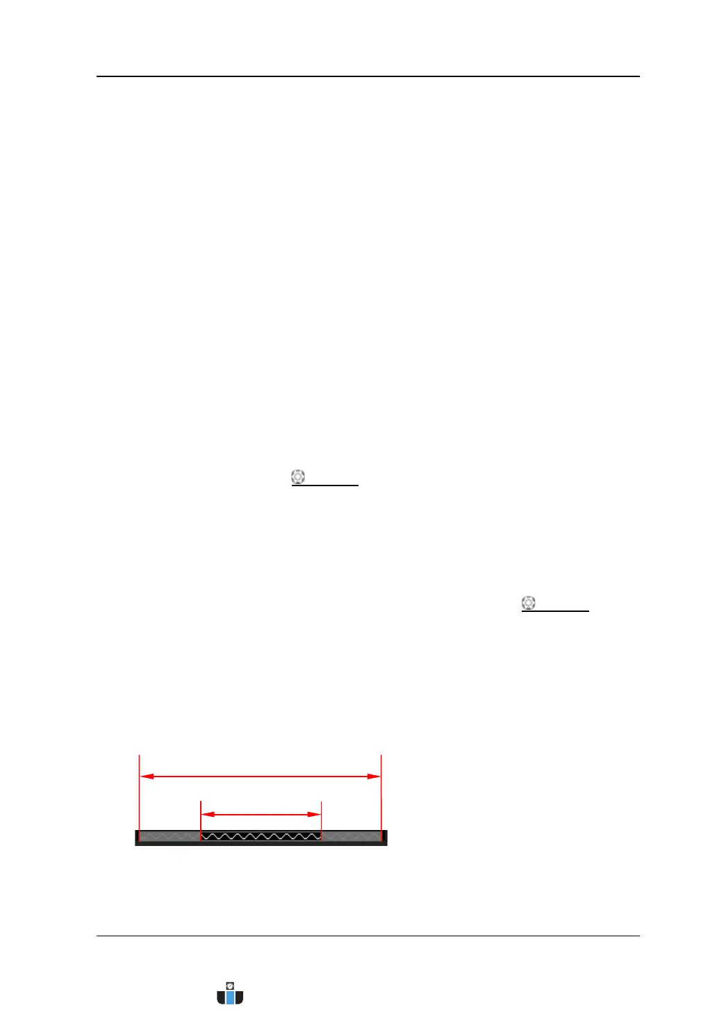
7. Waveform Memory
Provide the schematic diagram of the memory position of the waveform
currently on the screen in the memory.
8. Trigger Position
Display the trigger positions of the waveform in the waveform memory and on
Waveform on the Screen
www.calcert.com sales@calcert.com1.800.544.2843
0
5
10
15
20
25
30