Page 28.11C Chapter 28 Fuel System JUL 2020
28-23 Fuel Flow Meter Installation (continued)
D. Installation (continued)
Transducer (continued)
9. Perform appropriate functional checks per Garmin GTN-series or Avidyne IFD-
series moving-map navigation display Pilot’s Guide.
10. Install engine cowling assembly per § 53-21.
Adapter
1. Configure AIS-380 adapter if a replacement adapter or 660534HR-01 transducer
assembly was installed per Part E.
2. Turn battery & avionics switches off and pull out GPS (5 amp) circuit breaker
on panel.
3. Install hardware securing adapter to cabin bulkhead; verify security.
4. Connect airframe harness electrical connector to adapter; verify security.
5. Push in GPS circuit breaker (5 amp) on panel. Turn battery & avionics switches
on.
6. Perform appropriate functional checks per Garmin GTN-series or Avidyne IFD-
series moving-map navigation display Pilot’s Guide.
7. Install aft left back rest assembly per § 25-22.
E. Configuration
Configure AIS-380 fuel flow adapter per Shadin Avionics M833811-01 Installation
Manual Section 5.
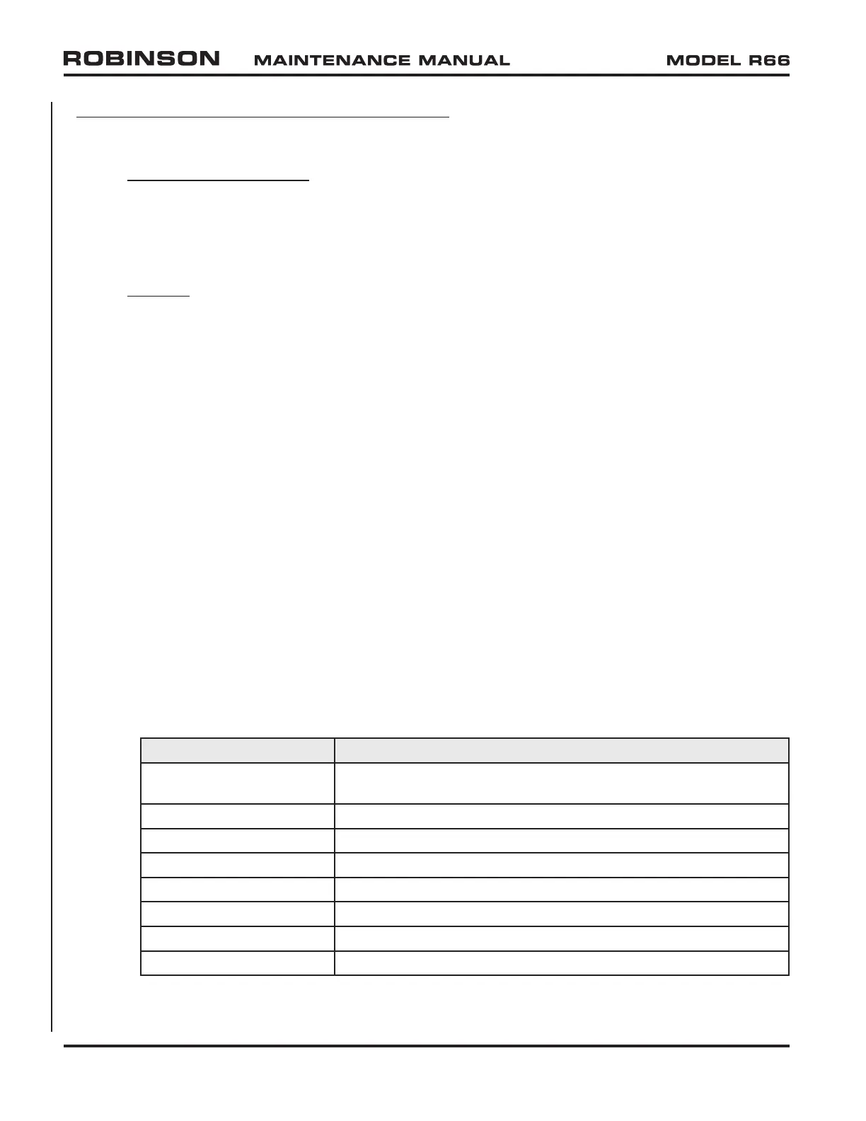
Make the following selections for R66 installation:
Field Selection
Serial Port Autopopulated (may change depending on connection
point to PC)
ARINC Leave at defaults
Fuel Flow Parameters Enabled
Engine Type Single Engine
Engine 1 K Factor See transducer*
Engine 2 K Factor See transducer*
Fuel Density (lbs/Gal) 6.71
Serial Output Format SHADIN_Z
* The K Factor is 1000 times the number printed on the transducer. For example,
a transducer with a K Factor of 9.63 is configured as 9630.