18-50 Tail Rotor Flight Control Rigging
Refer to R66 Illustrated Parts Catalog (IPC) Figures 67-29 thru 67-39.
18-51 Pedals
1. Refer to Figure 67-4. Insert a 3/16-inch diameter rigging pin through the hole in the
right-hand keel panel and the rigging pin holes in the C317-7 bellcrank.
2. Adjust the F121-9 push-pull tube as required to obtain a dimension of 5.24 ± 0.03 in.
from the lower forward NAS6604-9 bolt in C317-5 or C317-9 bellcrank and horizontal
pedal torque tube.
18-52 Forward Bellcrank
Remove the rigging pin and place the left pedal against its stop. Adjust the F121-11 push-
pull tube to obtain 1.08 - 1.18 inches between the end of the rod end and the bulkhead.
18-53 Intermediate Bellcrank
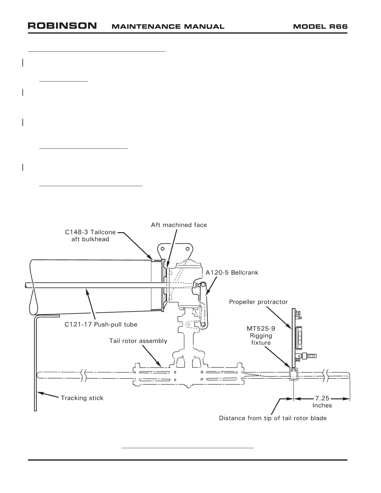
With left pedal at stop, adjust the C121-17 push-pull tube length as required to obtain
0.35 ± 0.03 inch between two faces of pitch control assembly and the housing.
FIGURE 18-11 TAIL ROTOR BLADE RIGGING
Page 18.28 Chapter 18 Track and Balance MAY 2015