OCT 2014 Chapter 96 Electrical System Page 96.9
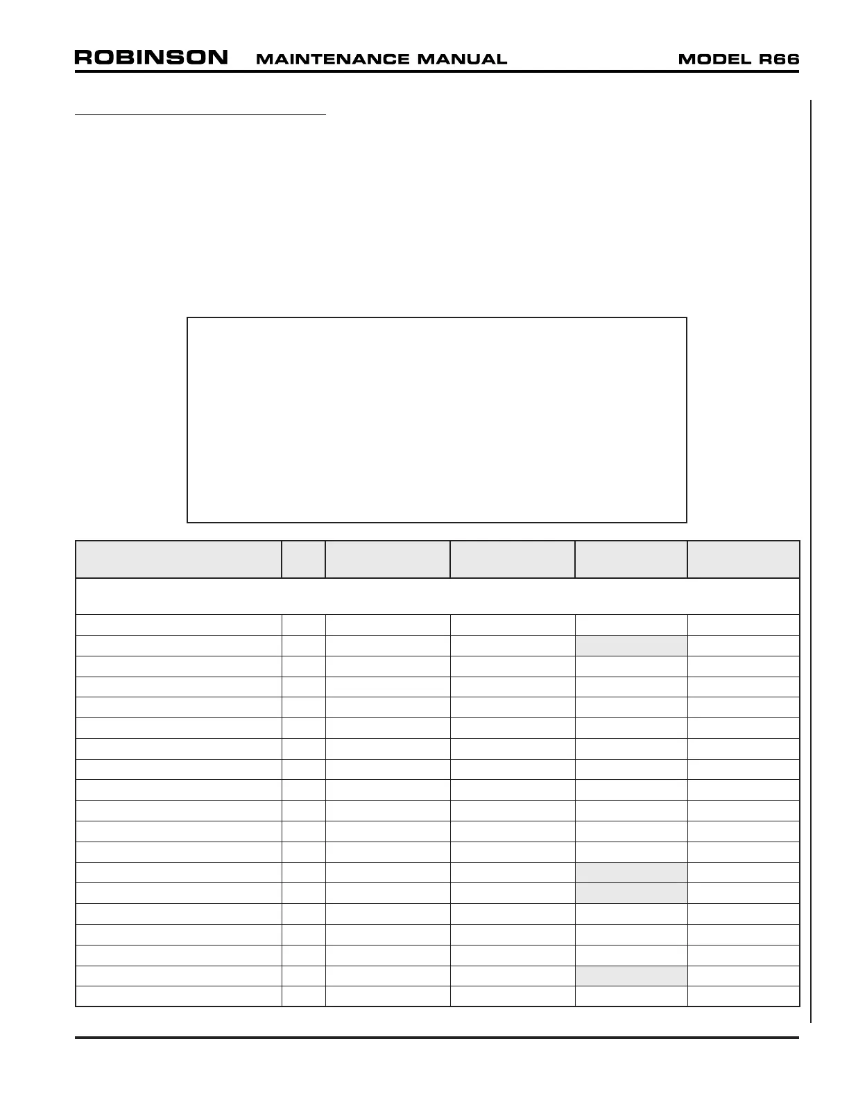
96-100 Electrical Load Analysis
To calculate the total electrical load for a specific helicopter, identify all items of equipment
installed on the helicopter from the table below and sum the corresponding continuous and
intermittent loads.
Maximum continuous generator load is 160 amps. Intermittent loads are provided for reference.
Alternately, the electrical load may be measured directly at the battery output terminal with the
generator switched off and all other equipment turned on. The measured load may be scaled
by the ratio of battery voltage to nominal system voltage to obtain a value that is compared
with the generator load limit.
WARNING
Field (non-factory) installation of electronic equipment can
be hazardous. Due to the compactness of the console and
tunnel containing the controls and wire bundles, installation
of any additional wires can interfere with flight controls.
Electronic tachometers, warning systems, and navigation
equipment essential to flight are sensitive to interference from
other electrical devices. The reliability and accuracy of the
tachometers is essential for safe operation of the helicopter,
and installation of an electrical device not tested and approved
by RHC may result in a hazardous condition.
EQUIPMENT QTY
CONTINUOUS
AMPS EACH
INTERMITTENT
AMPS EACH
CONTINUOUS
TOTAL
INTERMITTENT
TOTAL
MAIN BUS
WARNING LT PANEL 1 0.006 0.320 0.006 0.320
ROTOR BRAKE LT 1 --- 0.044 0.044
MAPLIGHT 1 0.020 0.020 0.020 0.020
INTERIOR DOME LT 1 0.020 0.020 0.020 0.020
OAT GAGE 1 0.150 0.150 0.150 0.150
ENGINE TORQUEMETER 1 0.050 0.050 0.050 0.050
INSTRUMENT CLUSTER 1 0.375 0.375 0.375 0.375
MOP SENDER 1 0.025 0.025 0.025 0.025
TORQ SENDER 1 0.025 0.025 0.025 0.025
LOW RPM UNIT W/HORN 1 0.045 0.160 0.045 0.160
AA12S-600 AUDIO PANEL 1 1.000 1.000 1.000 1.000
N2 GOVERNOR SYSTEM 1 0.000 0.087 0.000 0.087
N2 GOV ACTUATOR @ 12V 1 --- 0.150 0.150
N2 GOV RELAY @ 12V 1 --- 0.010 0.010
ANTI-ICE SOLENOID 1 0.670 0.670 0.670 0.670
HEATED PITOT 1 4.000 4.000 4.000 4.000
ENGINE HOUR METER 2 0.015 0.015 0.030 0.030
HYD CONTROL SOLENOID 1 --- 0.800 0.800
ENGINE MONITORING UNIT 1 0.180 0.180 0.180 0.180