CHAPTER 28
FUEL SYSTEM
28-00 Description
This chapter includes instructions for the removal and installation of the airframe fuel system
components. Refer to RR300 Series Operation and Maintenance Manual (OMM) for engine fuel
system maintenance procedures.
A single bladder-type crash-resistant fuel cell supplies fuel via gravity ow to the engine. The
fuel cell incorporates left and right vent ttings, a ller port, a fuel gage sender, a low-fuel
switch assembly, a sump drain, and a nger strainer at the fuel outlet. The low-fuel switch
assembly activates the low fuel segment on the annunciator panel, indicating approximately
ve gallons of usable fuel remaining. The vent ttings each have a roll-over valve to prevent
fuel leakage in any attitude.
The fuel cell is secured inside an aluminum structure. The ller cap is located under a cowl
door. The left and right side vent ttings are interconnected vent through two risers within the
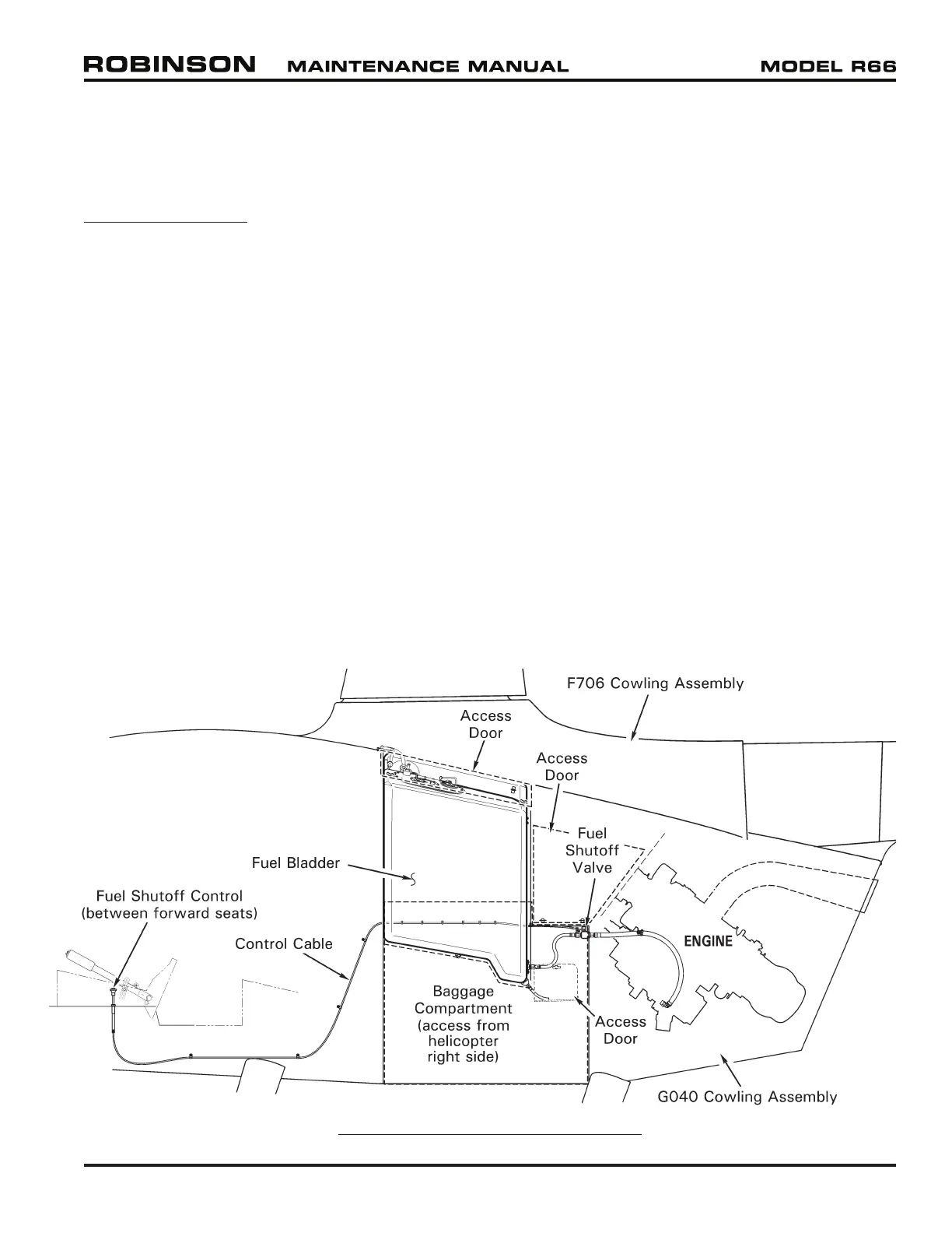
mast fairing. A fuel valve is located on the forward side of the rewall and is controlled by a
push-pull cable control at the base of the collective stick.
The engine incorporates a fuel pump assembly with an inlet lter. A differential pressure
switch illuminates the fuel lter warning light if the lter becomes contaminated.
A single drain allows fuel sampling from the low point in the fuel cell. The drain tube is
accessible via a left side cowl door. The drain is opened by extending the plastic tube clear of
the aircraft and pushing up on the drain.
25 OCT 2010 R66 Maintenance Manual Chapter 28 Fuel System Page 28.1
FIGURE 28-1 FUEL SYSTEM OVERVIEW