CHAPTER 62
MAIN ROTOR
62-00 Description
The main rotor has two all-metal blades and a forged-aluminum hub. Blades mount to the hub
by coning hinge; the hub mounts to the main rotor shaft by teeter hinge. Coning and teeter
hinges have self-lubricated bearings inside the hub.
The leading edge of the main rotor blade is a corrosion and erosion resistant stainless-steel
spar. Aluminum skins are bonded to the spar approximately one inch aft of the leading edge,
to the aluminum honeycomb core, and to the forged-aluminum root tting.
Each blade has six pitch change bearings that attach to a forged, stainless-steel spindle. The
bearings and part of the spindle are submerged in oil inside the root tting housing. The housing
is sealed with an elastic boot. The spindle tusk contacts an aluminum droop stop attached to
the main rotor shaft, to minimize teetering when blades are at rest or turning at low RPM.
62-10 Main Rotor Blades
WARNING
Due to potentially destructive results, use of blade tape (anti-
erosion tape) is prohibited.
A. Removal
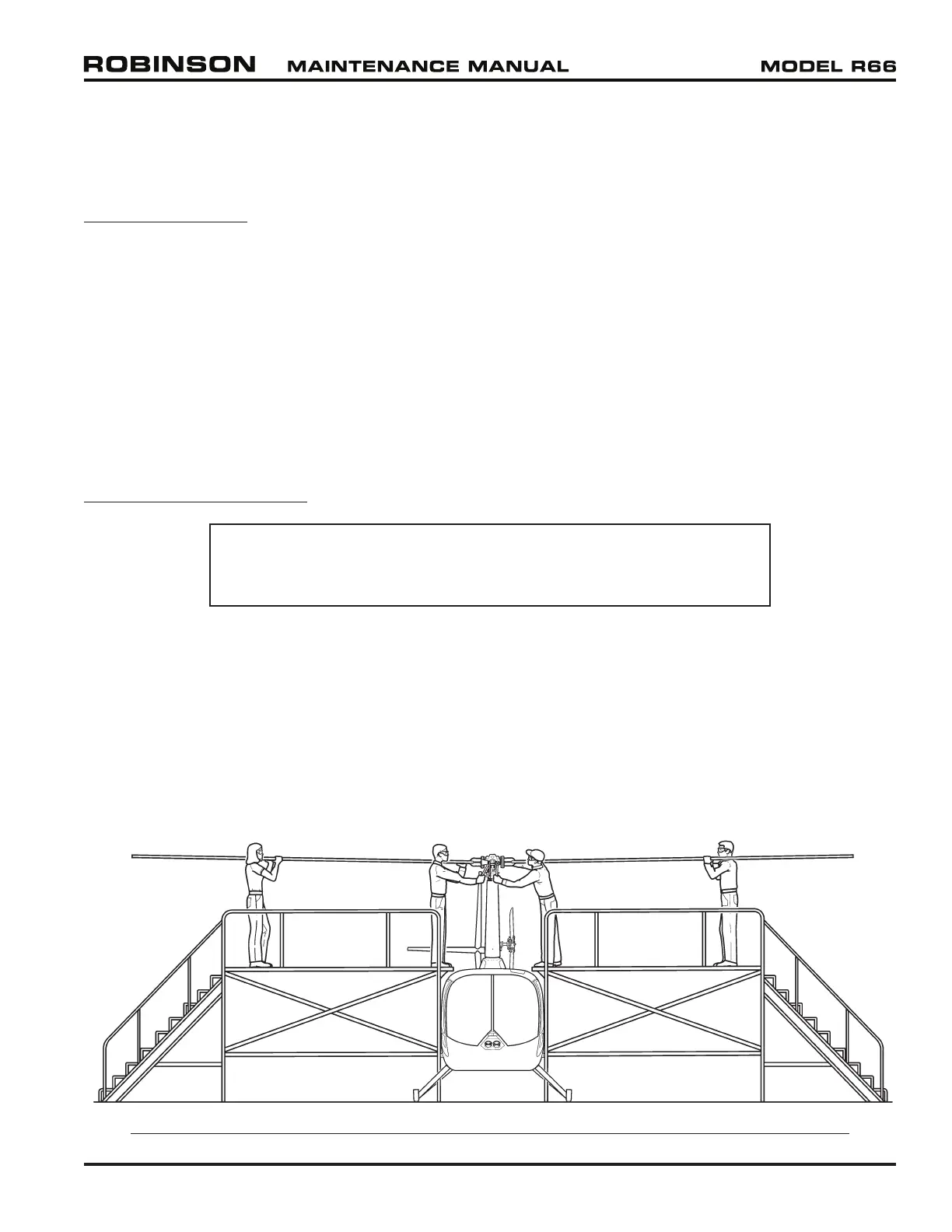
Refer to Figure 62-1. Four people will be required to remove the blades. One person must
support the blade approximately 2/3 its length from the root while another supports the
root and removes or installs the attached bolt.
1. Mark one blade and its corresponding hinge nut & bolt, pitch link and rotor head location
with a colored marker, such as a grease pencil and, mark as “X”. Using a different color
marker, mark as “O”, on the other blade, nut, bolt, pitch link and rotor head location.
2. Disconnect pitch links from each main rotor blade.
FIGURE 62-1 SUPPORTING MAIN ROTOR BLADES DURING BLADE REMOVAL OR INSTALLATION
25 OCT 2010 R66 Maintenance Manual Chapter 62 Main Rotor Page 62.1