63-11 (Engine Driveline) Forward Flex Plate Shimming (continued)
5. Evaluate flange straightness by calculating the difference between the 3 o’clock
positions in steps 4a and 4b. Also calculate the difference between the 9 o’clock
positions in steps 4a and 4b. If either calculated difference exceeds 0.015 inch, either
one or both flanges are bent and require replacement.
6. Using the smaller average gap from step 4a or 4b, subtract the flex plate average
thickness determined in step 3:
Smaller average gap between flange arms (step 4a or 4b) inch
Subtract flex plate average thickness (step 3) − inch
Total = inch
7. Select shims per Table 63-1 and install forward A947-2 flex plate assembly. Standard
torque nuts and palnuts per § 20-32 and torque stripe per Figure 5-1. Remove F642-1
(engine) shaft weldment temporary support.
WARNING
Shim both arms of flanges equally. All fasteners must meet
torque requirements given in § 20-33.
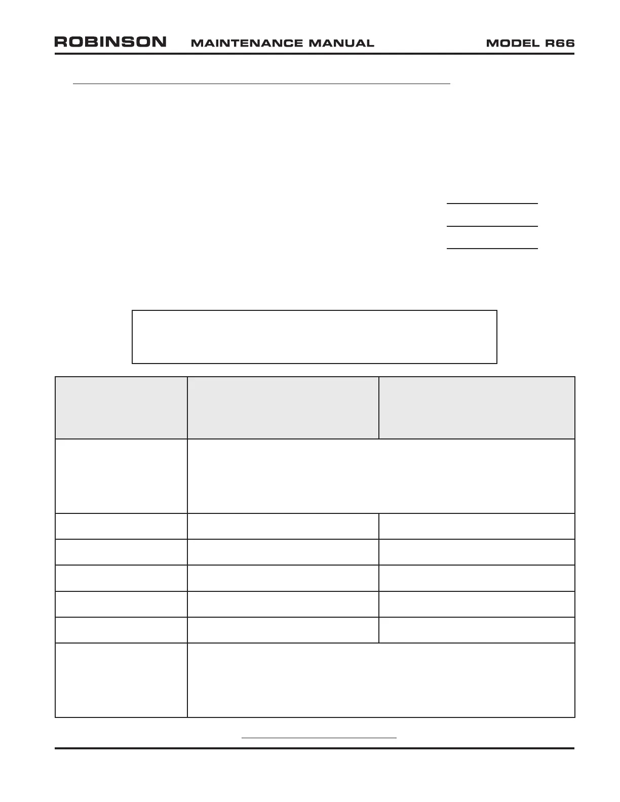
Calculated
Dimension
Shim required between
forward A947-2 flex plate and
F910-1 (main gearbox) yoke
Shim required between
forward A947-2 flex plate and
F642-1 (engine) shaft weldment
forward flange
−0.041 inch or greater
negative number
NAS1149F0432P washer between aft A947-2 flex plate assembly
and F642-1 (engine) shaft weldment aft flange and/or F018-1 clutch
assembly yoke may be relocated under nut as required to achieve
−0.040 / 0.000 inch calculated dimension. Relocate washers as
required, and repeat steps 4 thru 7.
−0.040 / 0.000 inch None None
+0.001 / +0.029 inch NAS1149F0432P washer None
+0.030 / +0.059 inch NAS1149F0432P washer NAS1149F0432P washer
+0.060 / +0.090 inch NAS1149F0463P washer NAS1149F0432P washer
+0.091 / +0.121 inch NAS1149F0463P washer NAS1149F0463P washer
+0.122 inch or greater
positive number
NAS1149F0432P washer between aft A947-2 flex plate assembly and
F642-1 (engine) shaft weldment aft flange and/or F018-1 clutch assembly
yoke may be exchanged with NAS1149F0463P washer as required to
achieve −0.040 / 0.000 inch calculated dimension. Exchange washers as
required, and repeat steps 4 thru 7.
MAY 2015 Chapter 63 Main Rotor Drive System Page 63.3
TABLE 63-1 ENGINE DRIVELINE