Roche Diagnostics May 2009
Service Manual · Version 9.0 B-65
cobas b 221 system 4 Components
Peristaltic pumps (PP)
6
Raise the central measuring unit forward until it clicks audibly into place.
7
Disassemble the fan shield.
e
For instructions, see Replacing the main fan unit on page B-110.
8
Remove the plug on the back of the pump.
9
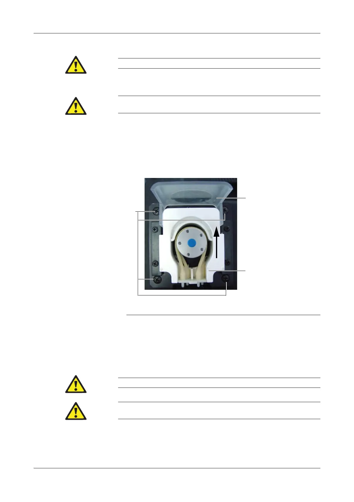
Open the locking lever (Plexiglas cover) of the peristaltic pump and slide the
linear clamp (white plastic part) up (see below).
10
Remove the pump tube.
11
Unscrew the four screws holding the peristaltic pump, slide it up and pull it out
forwards (see above, A).
Use the reverse order for assembly.
Do not remove the fastening screws completely, because they are secured against loss.
The sample inlet path must be removed at this time, otherwise it will be destroyed by folding the
central measuring unit out.
A Four screws holding the peristaltic pump
B Locking lever
C Linear clamp
Figure B-46 Peristaltic pump
When positioning the pump tube around the pump head, make sure that the tubes are not crossed.
Test the function of the peristaltic pump with
h
[System] > [Component test] > [Aggregates] >
[Peristaltic pumps].
 Loading...