Roche Diagnostics May 2009
B-112 Service Manual · Version 9.0
4 Components cobas b 221 system
Replacing the actuator bus main controller cable
12
Release the valve bus connector cable on the V4/V6 actuator board and remove
the cable (see above).
Use the reverse order for assembly.
Replacing the actuator bus main controller cable
1
Remove the rear panel.
e
For instructions, see Removing the rear panel on page B-20.
2
Rotate the T&D lock on the T&D module 90 degrees to the right.
e
For details, see Figure B-4 on page B-22.
3
Carefully pull the sample inlet path out to the right and remove it.
4
Unscrew the three screws holding the central measuring unit.
e
For details, see Figure B-2 on page B-20.
5
Raise the central measuring unit forward until it clicks audibly into place.
6
Remove the light guide conduit with the COOX light guide.
e
For instructions, see Replacing the primary light guide on page B-56.
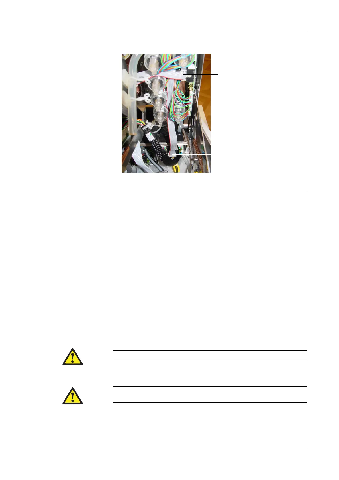
A Plug connector on the measuring chamber
cartridge valve unit
B Plug connector on the V4/V6 actuator
board
Figure B-84 Valve bus cable
Do not remove the fastening screws completely, because they are secured against loss.
The sample inlet path must be removed at this time, otherwise it will be destroyed by folding the
central measuring unit out.
 Loading...