Roche Diagnostics May 2009
B-90 Service Manual · Version 9.0
4 Components cobas b 221 system
Mainboard unit
10
Disconnect all cable connectors fixed to the mainboard with plugs on the
modules.
11
Press the mainboard unit to the left or right to release it from the retainer pins.
12
Remove the mainboard unit.
Use the reverse order for assembly.
The default settings for all items of the DIP switch are "Off".
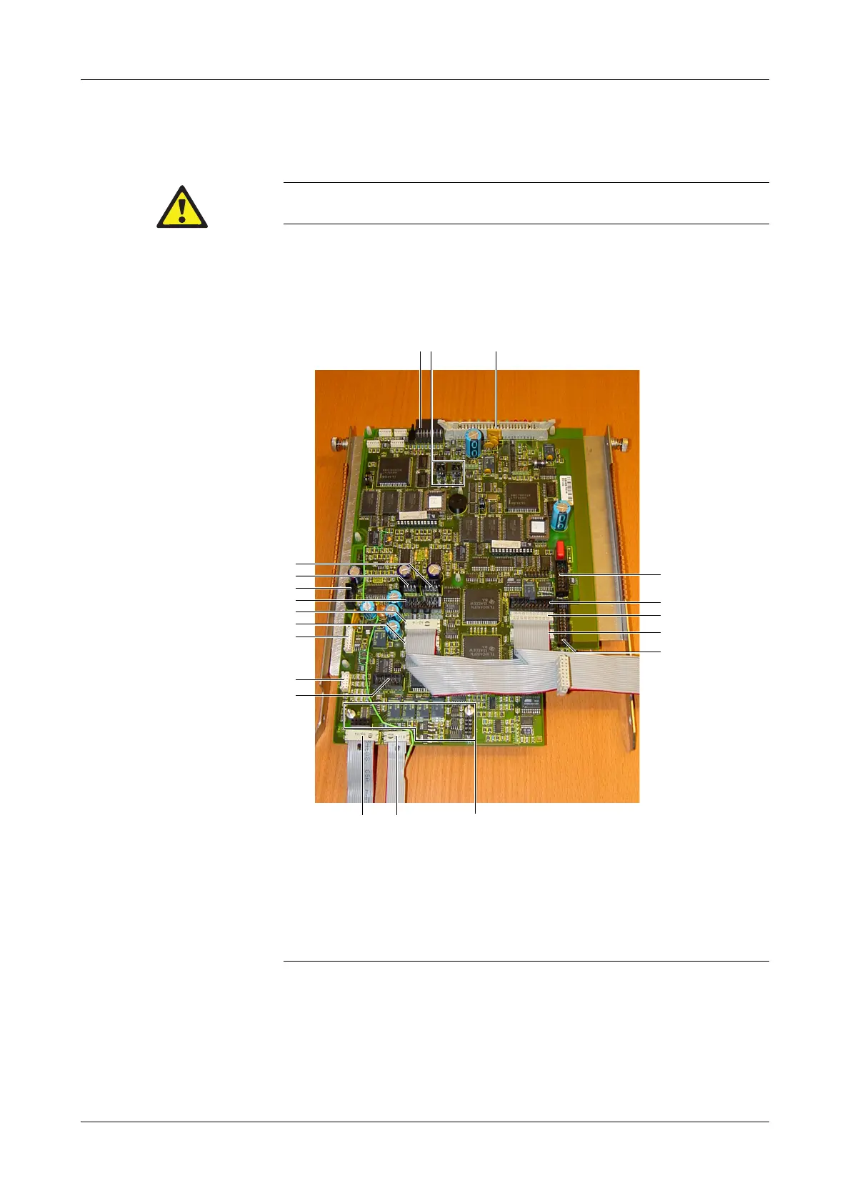
The BG and ISE module plug connectors on the mainboard are permanently attached: do not pull
them off!
A Sample sensor board
B Peltier tHb/SO
2
–COOX
C Actuator bus HS
D tHb/SO
2
–COOX
E Sense 2
F Sense 1
G Measuring chamber BG
H Measuring chamber ISE
I Measuring chamber MSS
J PP main
K PP MSS out
L PP MSS in
M DIP switch
N Fan 1 / fan 2
O Interface unit
P Valve bus
Q Peltier MSS
R Peltier ISE
S Peltier BG
T Peltier SD
Figure B-67 Mainboard connectors
 Loading...