Roche Diagnostics May 2009
A-42 Service Manual · Version 9.0
2 Fluid actions cobas b 221 system
Calibration
CAL 2/CAL 3/CAL 4 Calibration
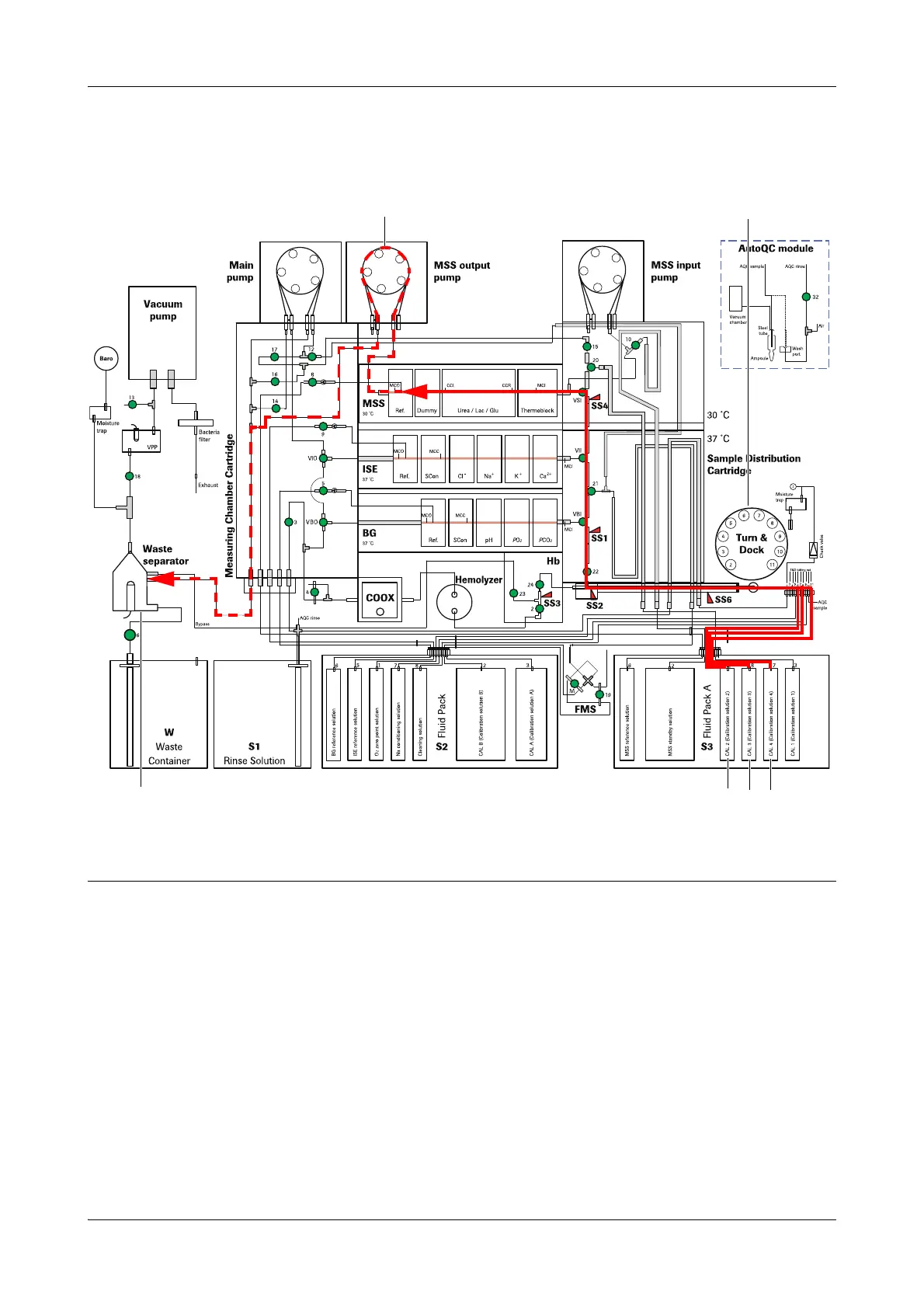
CAL 2 Calibration This procedure determines the linearity of the sensors. CAL 2 is aspirated from the
S3 Fluid Pack A via the T&D disk (position 6), sample inlet path and sample
distributor into the MSS measuring chamber and measured.
CAL 3 Calibration This procedure determines the interference sensitivity of the sensors. CAL 3 is
aspirated from the S3 Fluid Pack A via the T&D disk (position 8), sample inlet path
and sample distributor into the MSS measuring chamber and measured.
CAL 4 Calibration This procedure determines the interference sensitivity of the sensors. CAL 4 is
aspirated from the S3 Fluid Pack A via the T&D disk (position 11), sample inlet path
and sample distributor into the MSS measuring chamber and measured.
A MSS output pump
B T&D module (CAL 2=Pos.6, CAL 3=Pos.8, CAL 4= Pos.11)
C Waste separator
D CAL 2
E CAL 3
F CAL 4
Figure A-25 CAL 2/CAL 3/CAL 4 Calibration
 Loading...