178 Rockwell Automation Publication 2198-UM005C-EN-P - February 2022
Appendix A Interconnect Diagrams
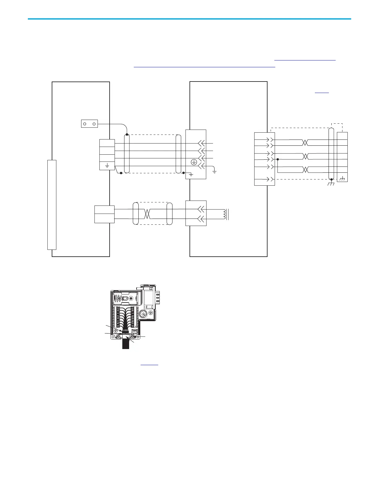
The 2090-DANFCT-Sxx feedback cable is equipped with a drive-end connector
that is not compatible with the 15-pin (MFB) feedback connector. To provide
battery backup to the encoder, you can remove the drive-end connector and
prepare the cable shield and conductors for wiring to the 2198-K53CK-D15M
feedback connector kit. For more information, see Cable Preparation for
Kinetix TL and TLY Motor Power Cables on page 86.
Figure 87 - Kinetix 5300 with Kinetix TL Rotary Motors
U
V
W
GND
U
V
W
1
2
MBRK +
MBRK -
Brown
Black
Blue
Green/Yellow
White
Black
Shield
1
2
3
4
5
6
7
8
9
10
11
12
13
14
15
8
7
6
5
4
3
2
1
10
11
12
13
14
+
--
GRAY
WHT/GRAY
7
8
14
6
9
ORANGE
WHT/ORANGE
14
BAT+
BAT-
+5VDC
ECOM
SHIELD
BAT+
BAT-
SD+
SD-
BROWN
WHT/BROWN
12
13
5
10
1
2
3
5
1
2
BR+
BR-
Motor Brake
Motor Brake
Connector
Motor Power
Connector
TL-Axxxx-B (230V)
Servo Motors with
High-resolution Feedback
Motor Feedback
(MFB) Connector
Three-phase
Motor Power
Motor
Feedback
Refer to connector kit
illustration (lower left)
for proper grounding technique.
Grounding Technique for
Feedback Cable Shield
Refer to table on page 169
for
note information.
2090-DANFCT-Sxx (standard)
Flying-lead Feedback Cable
(with drive-end connector removed)
Note 8
2090-DANPT-16Sxx
Motor Power Cable
Note 8
Cable Shield
Clamp
Note 5
2198-Cxxxx-ERS
Kinetix 5300 Servo Drives
Refer to Kinetix 5300 Feedback Connector Kit
Installation Instructions, publication 2198-IN023
, for
connector kit specifications.
2198-K53CK-D15M Feedback
Connector Kit
Use the 2198-K53CK-D15M
feedback connector kit
with flying-lead cables.
2090-DANBT-18Sxx
Motor Brake Cable
Note 8
360° exposed shield that
is secured under clamp.
Clamp Screws (2)
Clamp
Tie Wrap
 Loading...


