26 Rockwell Automation Publication 2198-UM005C-EN-P - February 2022
Chapter 2 Plan the Kinetix 5300 Drive System Installation
• Drive-to-motor cables must not exceed 50 m (164 ft), depending on input
voltage and feedback type. For specifications, refer to Maximum Cable
Lengths on page 82.
• Use high-frequency (HF) bonding techniques to connect the modules,
enclosure, machine frame, and motor housing, and to provide a low-
impedance return path for high-frequency (HF) energy and reduce
electrical noise.
Bond drive and line filter grounding screws by using a braided ground
strap as shown in Figure 36 on page 71
.
Refer to the System Design for Control of Electrical Noise Reference Manual,
publication GMC-RM001
, to better understand the concept of electrical noise
reduction.
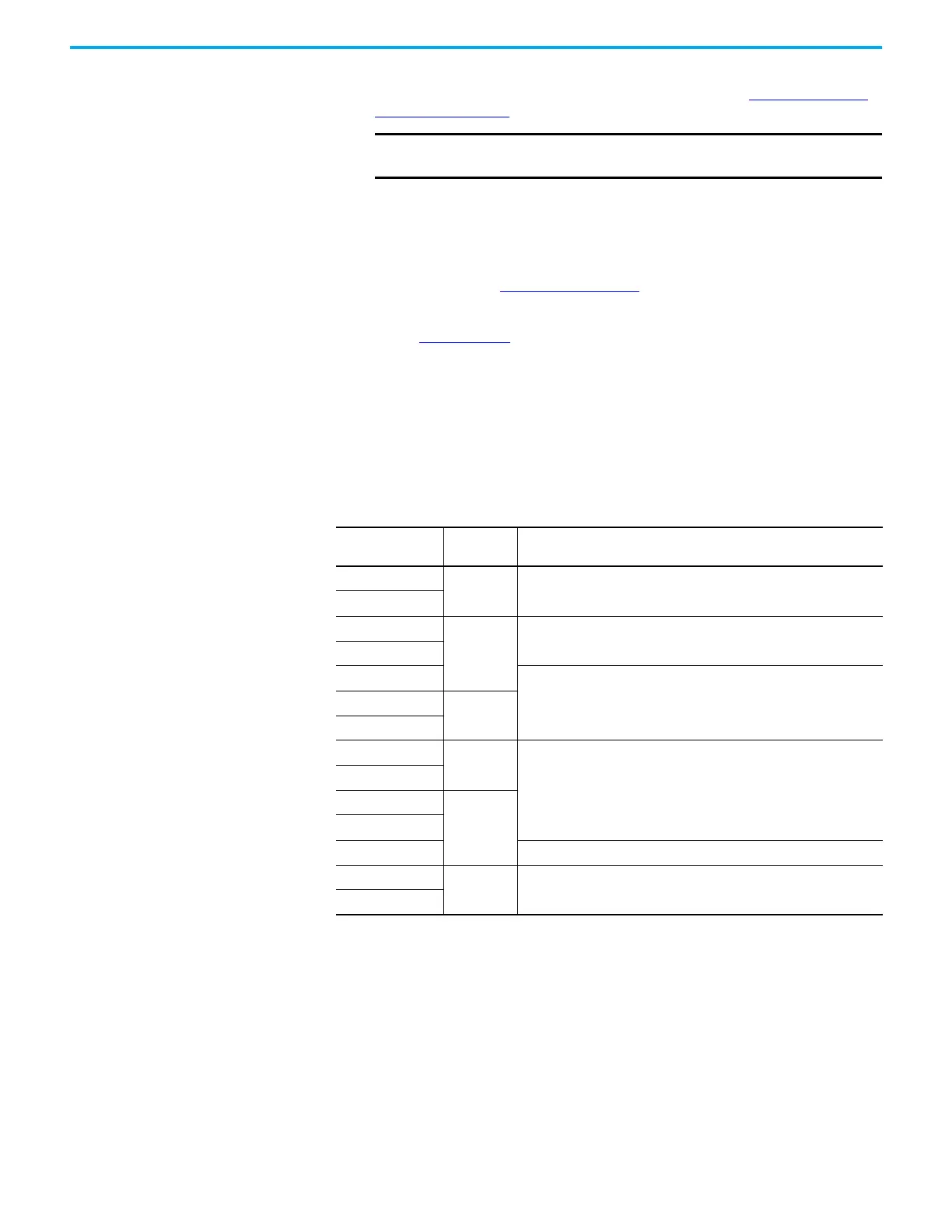
AC Line Filter Selection
An AC line filter is required to meet CE requirements. Install an AC line filter
with 50 mm (1.97 in.) minimum clearance between the drive and filter.
Minimize the cable length as much as possible.
Table 6 - AC Line Filter Selection
IMPORTANT System performance was tested at these cable length specifications.
These limitations also apply when meeting CE requirements.
Drive Cat. No. Frame Size
AC Line Filter
Cat. No.
2198-C1004-ERS
1 2198-DB08-F
2198-C1007-ERS
2198-C1015-ERS
2
2198-DBR20-F
2198-C1020-ERS
2198-C2030-ERS
2198-DBR40-F2198-C2055-ERS
3
2198-C2075-ERS
2198-C4004-ERS
1
2198-DB08-F
2198-C4007-ERS
2198-C4015-ERS
22198-C4020-ERS
2198-C4030-ERS 2198-DBR20-F
2198-C4055-ERS
32198-DBR40-F
2198-C4075-ERS
 Loading...


