Rockwell Automation Publication 2198-UM005C-EN-P - February 2022 183
Appendix A Interconnect Diagrams
Incremental encoders include S1, S2, and S3 (Hall) signals, so feedback cables
with additional conductors are specified.
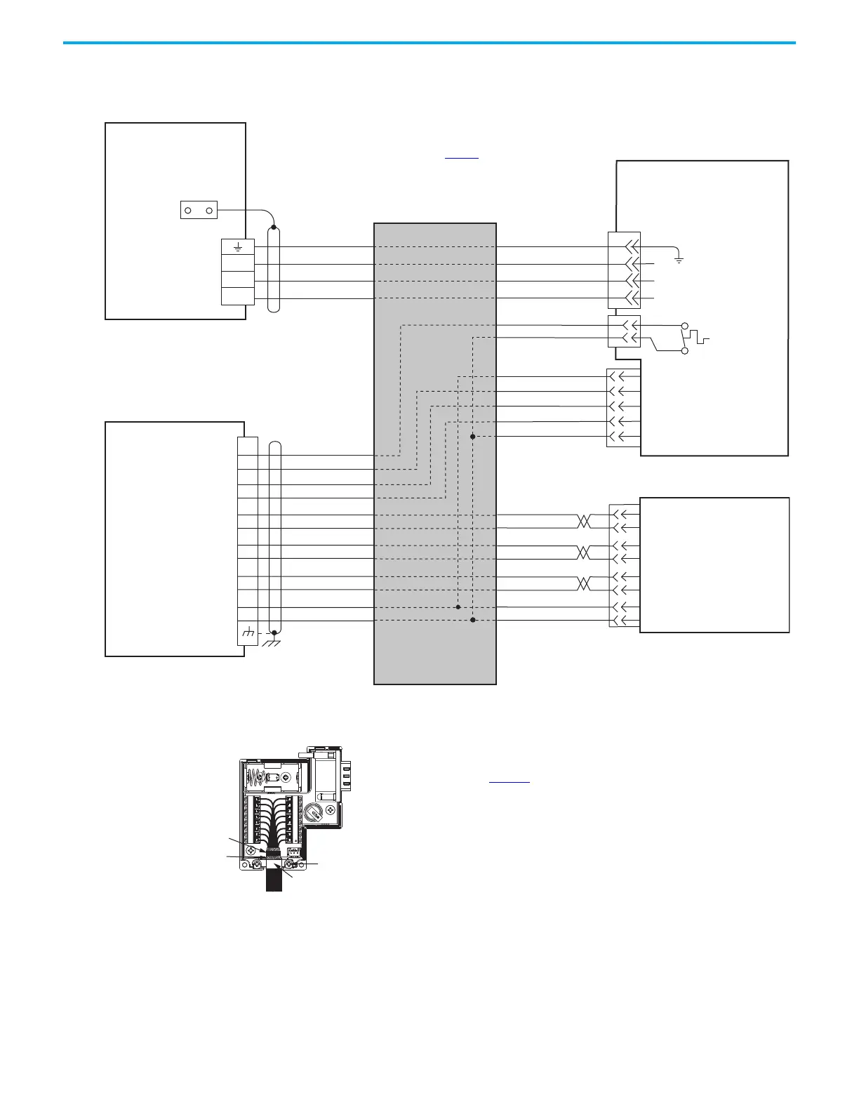
Figure 92 - Kinetix 5300 with Kinetix LDC or Kinetix LDL Linear Motors (flying-lead cables)
W
V
U
GND
W
V
U
GREEN/YELLOW
BLACK
WHITE
RED
BLACK
BLACK
RED
WHITE
BLUE
ORANGE
BLACK
W
V
U
TS+
TS-
POWER
S1
S2
S3
COM
SIN+
SIN-
COS+
COS-
IM+
IM-
POWER
COM
TS+
S1
S2
S3
13
8
12
11
(AM+)
(AM-)
(BM+)
(BM-)
1
2
3
4
5
10
14
6
SIN+
SIN-
COS+
COS-
IM+
IM-
POWER
COM
(AM+)
(AM-)
(BM+)
(BM-)
8
7
6
5
4
3
2
1
10
11
12
13
14
+
--
Motor Power
Connector
Cable Shield
Clamp
Note 5
LDC-Cxxxxxx-xHTx0 or
LDL-xxxxxxx-xHTx0
Linear Motor Coil with
Sin/Cos or TTL External Encoder
and Flying-lead Cables
Three-phase
Motor Power
Motor Feedback
(MFB) Connector
Thermostat
Refer to table on page 169
for
note information.
External
Sin/Cos or (TTL)
Encoder
Hall Effect
Module
Wire as shown using
cable type appropriate for
your application.
2198-Cxxxx-ERS
Kinetix 5300 Servo Drives
2198-K53CK-D15M Feedback
Connector Kit
2198-Cxxxx-ERS
Kinetix 5300 Servo Drives
Grounding Technique for
Feedback Cable Shield
Use the 2198-K53CK-D15M
feedback connector kit
with flying-lead cables.
Refer to Kinetix 5300 Feedback Connector Kit
Installation Instructions, publication 2198-IN023
, for
connector kit specifications.
360° exposed shield that
is secured under clamp.
Clamp Screws (2)
Clamp
Tie Wrap
 Loading...


