Rockwell Automation Publication 2198-UM005C-EN-P - February 2022 43
Chapter 3 Mount the Kinetix 5300 Drive System
The connection system is comprised of three components:
• Input wiring connectors that plug into the leftmost drive and receive
input wiring for 24V DC.
• 24V DC T-connectors that plug into the drives downstream from the first
drive where 24V control power is shared.
• Bus bars that connect between drives to extend the 24V DC control power
from drive-to-drive.
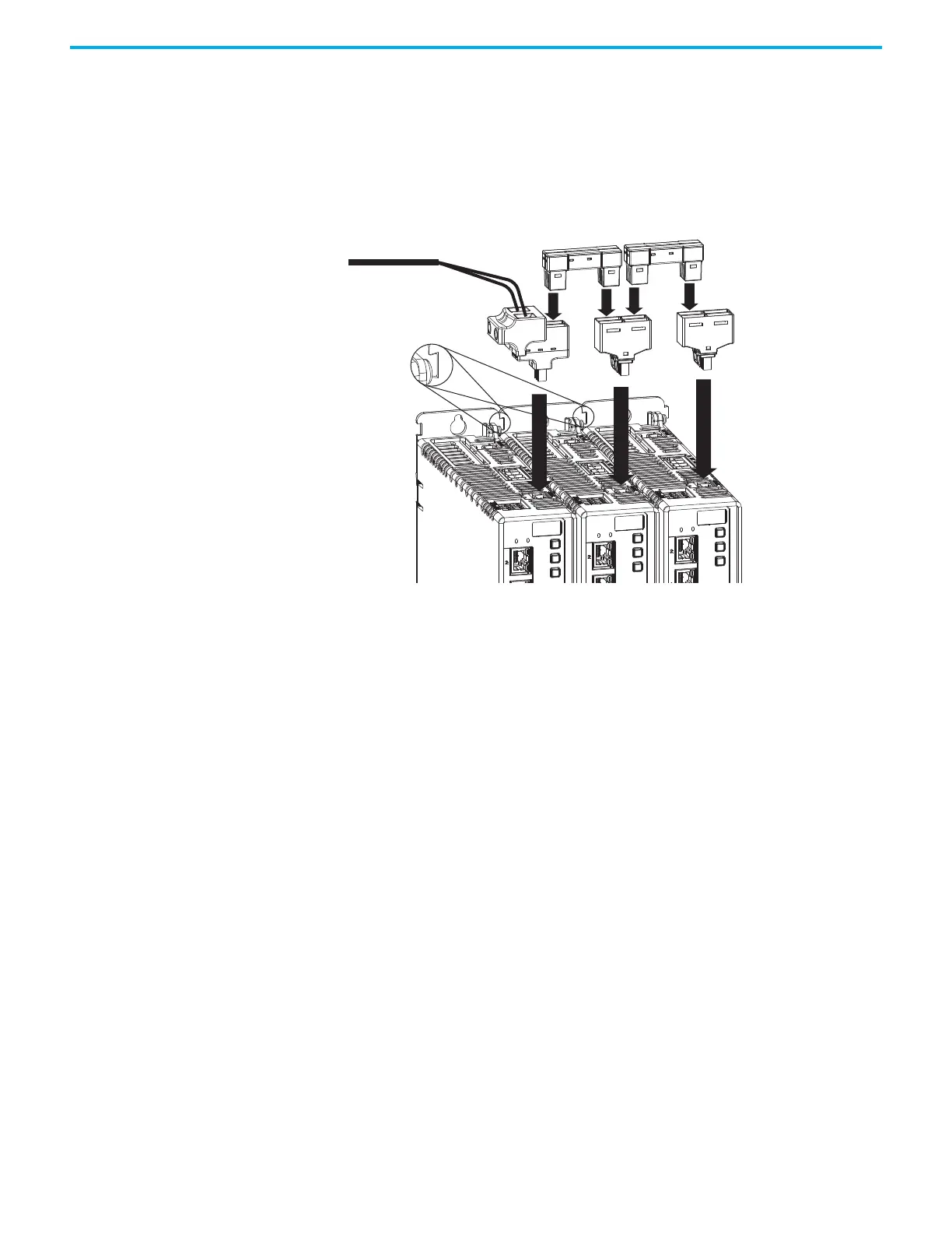
Figure 19 - Connection System Example
(1) Due to the extra width of frame 3 drives, bus-bar connectors between frame 3 drives are slightly longer than connectors between
frame 3, frame 2, and frame 1 drives.
The three components assemble from left to right across the drive system.
1. Attach wiring to input wiring connectors.
2. Insert input wiring connectors and T-connectors into the appropriate
drive connectors.
3. Insert bus-bars to connect between wiring connectors and T-connectors.
2198-Cxxxx-ERS Drive System (top view)
Frame 2 drives are shown.
Control Power Wiring Connector
Control Power T-connectors
Bus-bar Connectors
(1)
(frame 1 and 2 bus-bars are shown)
From 24V DC Supply
Zero-stack Tab
and Cutout Engaged
 Loading...


