Rockwell Automation Publication 440R-UM013G-EN-P - December 2022 55
Chapter 11 Troubleshooting
Table 11 - PWR/Fault Status Indicator Is Steady Red
Status
Indicator
Description Model Possible Causes Corrective Action
Steady red
Faults that are not
described in Table 12
and Table 13 on page 56
result in a steady red
status indicator.
All
• A momentary power interruption.
• Noise on the power or signal wires.
• Cycle power to clear the fault and return the GSR safety
relay to an operational state.
• Reconfigure the safety relay (see Configuration
on page 31).
• See additional information in Verify Grounding at the Power
Supply on page 57.
CI, DI, DIS, and SI
Short circuit has occurred, or is present, from
+24V DC (A1) to S11 or S21 or from 24V Common
(A2) to S11 or S21.
DIS
Short circuit has occurred, or is present, from
+24V DC (A1) to 14 or 24.
SI
Excessive capacitance from input wiring to
ground, but not enough to cause flashing red four
times.
Table 12 - PWR/Fault Status Indicator Is Flashing Red
Status Indicator Description Model Possible Causes Corrective Action
Flashing red 1 Hz
The GSR safety relay is
in Configuration mode.
All
• The safety relay is shipped from the factory
with no configuration.
• The configuration process was not completed
successfully.
Continue with the configuration process. Rotate the switches
to the desired positions and cycle power.
Flashing red 2
times
Invalid configuration. All
• Upon power-up, one or more of the rotary
switch settings do not agree with the value
that is stored in the EEPROM.
• Connections at S11 and S21 were swapped after
configuration.
• Return the switches/wiring to their proper settings/
terminals and cycle power.
(1)
• Reconfigure the safety relay.
Flashing red 3
times
Invalid configuration.
DI, DIS
• During configuration, the Logic switch is set
for IN1 OR IN2 (position 1, 3, 5, or 7), but the
inputs are wired for safety mats.
• If the inputs are not closed during
configuration, the DI and DIS safety relays
show this fault on the next power cycle if the
inputs are closed.
• Reconfigure the safety relays for IN1 AND IN2 (position 2, 4,
6, or 8). See Configuration
on page 31
• See additional information in Safety Mats on page 21.
EMD
A jumper was added from B1 to B2 after
configuration and power was later cycled.
Flashing red 4
times
Cross fault.
All
• You modified the wiring after configuration.
• You wired up one or more input connections as
a safety mat. When you stepped on the safety
mat, the GSR safety relay went to Fault mode.
• Check the wiring.
• Remove the short circuit and cycle the input device, or
cycle the power.
• See additional information in Check Voltage-free Contacts
on page 58.
CI, DI, DIS,
and SI
• A short circuit occurred (and is no longer
present) or is present from S11 to S21.
• Excessive capacitance is detected on input
wiring to ground. The pulse tests waveform is
distorted.
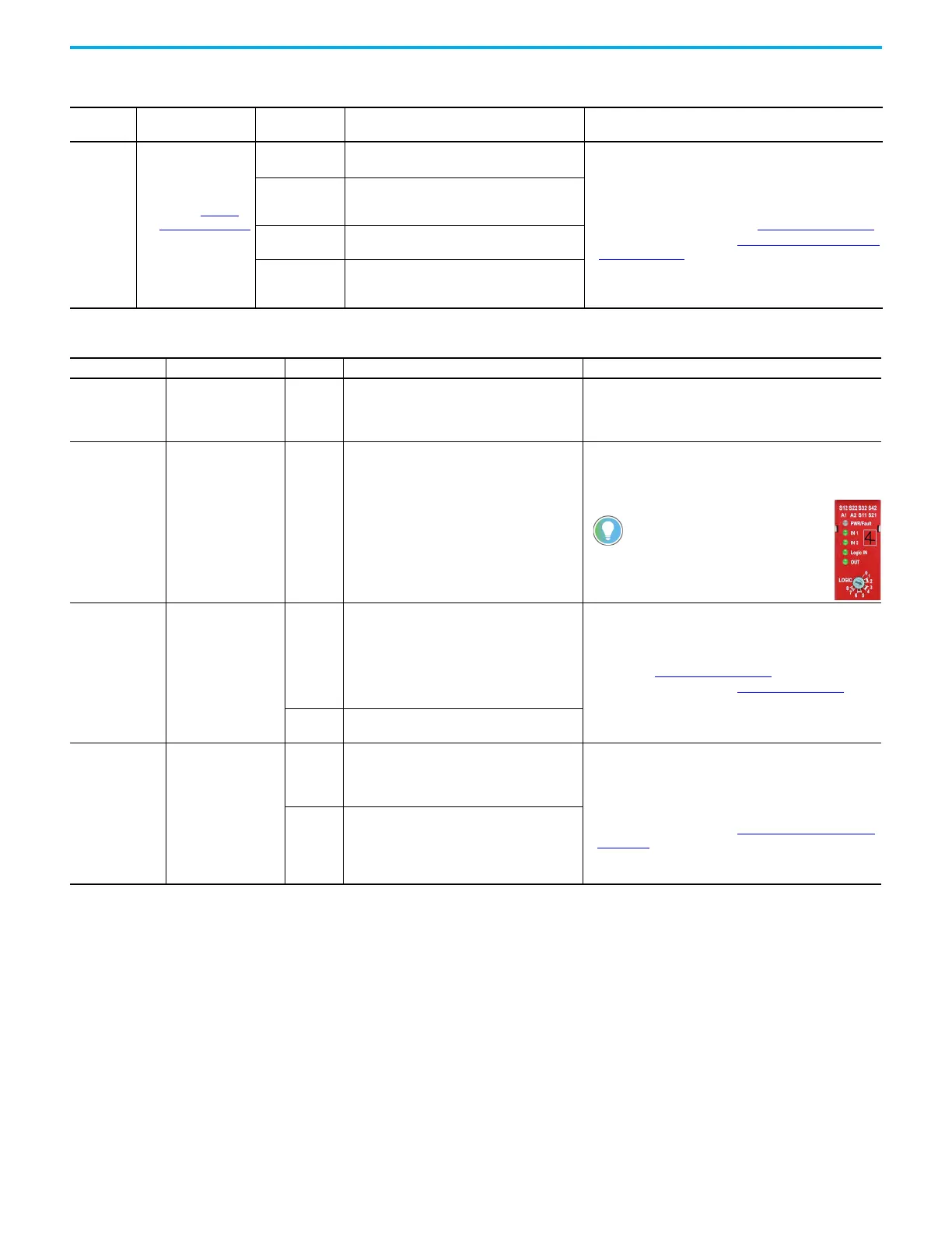
Record the switch setting on the front
face. For example, the logic setting is set
to 3, but it must be set to 4.

 Loading...


