16 Rockwell Automation Publication 520-UM001K-EN-E - August 2021
Chapter 1 Installation/Wiring
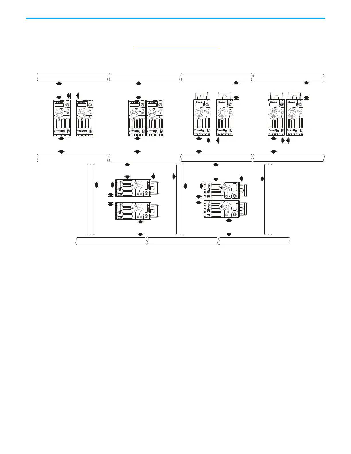
Minimum Mounting Clearances
See Product Dimensions on page 184 for mounting dimensions.
(1) For Frame E with Control Module Fan Kit only, clearance of 95 mm (3.7 in.) is required.
(2) For Frame E with Control Module Fan Kit only, clearance of 12 mm (0.5 in.) is required.
25 mm
(1.0 in.)
25 mm
(1.0 in.)
(2)
(2)
25 mm
(1.0 in.)
50 mm
(2.0 in.)
50 mm
(2.0 in.)
(1)
50 mm
(2.0 in.)
(1)
50 mm
(2.0 in.)
(1)
50 mm
(2.0 in.)
50 mm
(2.0 in.)
50 mm
(2.0 in.)
Esc
Sel
Esc
Sel
Esc
Sel
Esc
Sel
50 mm
(2.0 in.)
50 mm
(2.0 in.)
50 mm
(2.0 in.)
50 mm
(2.0 in.)
E
s
c
S
e
l
E
s
c
S
e
l
50 mm
(2.0 in.)
50 mm
(2.0 in.)
50 mm
(2.0 in.)
50 mm
(2.0 in.)
50 mm
(2.0 in.)
(1)
Esc
S
el
Esc
Se
l
Esc
Sel
Esc
Sel
Esc
Sel
Esc
Sel
Vertical, Zero Stacking
No clearance between drives.
Horizontal, Zero Stacking with
Control Module Fan Kit
No clearance between drives.
Vertical Vertical, Zero Stacking with
Control Module Fan Kit
No clearance between drives.
Vertical with Control Module Fan Kit
Horizontal with Control Module Fan Kit

 Loading...


