208 Rockwell Automation Publication 520-UM001K-EN-E - August 2021
Appendix C RS485 (DSI) Protocol
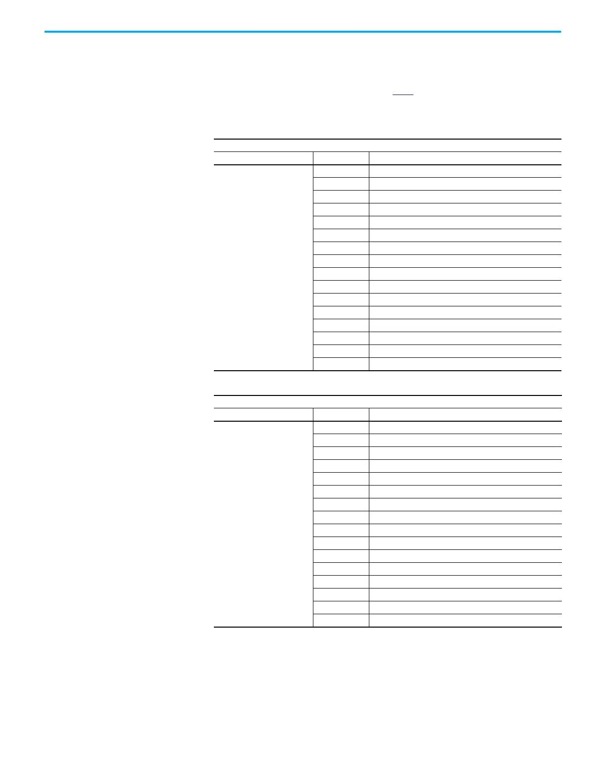
Reading (03) Logic Status
Data
The PowerFlex 520-series drive Logic Status data can be read through the
network by sending Function Code 03 reads to register address 2100H (Logic
Status). PowerFlex 523 drives support only Velocity bit definitions.
PowerFlex 525 drives can use Parameter C122
[Cmd Stat Select] to select either
Velocity or Position bit definitions.
Velocity Bit Definitions
Comm Logic Status – C122 = 0 “Velocity”
Address (Decimal) Bit(s) Description
2100H (8448)
0 1 = Ready, 0 = Not Ready
1 1 = Active (Running), 0 = Not Active
2 1 = Cmd Forward, 0 = Cmd Reverse
3 1 = Rotating Forward, 0 = Rotating Reverse
4 1 = Accelerating, 0 = Not Accelerating
5 1 = Decelerating, 0 = Not Decelerating
6Not Used
7 1 = Faulted, 0 = Not Faulted
8 1 = At Reference, 0 = Not At Reference
9 1 = Main Freq Controlled by Active Comm
10 1 = Operation Cmd Controlled by Active Comm
11 1 = Parameters have been locked
12 Digital Input 1 Status (DigIn TermBlk 05)
13 Digital Input 2 Status (DigIn TermBlk 06)
14 Digital Input 3 Status (DigIn TermBlk 07)
15 Digital Input 4 Status (DigIn TermBlk 08)
Position Bit Definitions
Comm Logic Status – C122 = 1 “Position”
Address (Decimal) Bit(s) Description
2100H (8448)
0 1 = Ready, 0 = Not Ready
1 1 = Active (Running), 0 = Not Active
2 1 = Cmd Forward, 0 = Cmd Reverse
3 1 = Rotating Forward, 0 = Rotating Reverse
4 1 = Accelerating, 0 = Not Accelerating
5 1 = Decelerating, 0 = Not Decelerating
6 1 = Forward Travel Position, 0 = Reverse Travel Position
7 1 = Faulted, 0 = Not Faulted
8 1 = At Reference, 0 = Not At Reference
9 1 = At Position, 0 = Not At Position
10 1 = At Home, 0 = Not At Home
11 1 = Drive Homed, 0 = Not Drive Homed
12 1 = Sync Hold, 0 = Not Sync Hold
13 1 = Sync Ramp, 0 = Not Sync Ramp
14 1 =Traverse On, 0 = Traverse Off
15 1 = Traverse Decel, 0 = Not Traverse Decel

 Loading...


