212 Rockwell Automation Publication 520-UM001K-EN-E - August 2021
Appendix D Velocity StepLogic, Basic Logic and Timer/Counter Functions
Velocity StepLogic Using
Timed Steps
To activate this function, set one of the three speed reference sources,
parameter P047, P049, or P051[Speed Referencex] to 13 “Step Logic” and
activate that speed reference source. Three parameters are used to configure
the logic, speed reference and time for each step.
• Logic is defined using parameters L180...L187 [Stp Logic x].
• Preset Speeds are set with parameters A410...A417 [Preset Freq 0...7].
• Time of operation for each step is set with parameters L190...L197 [Stp
Logic Time x].
The direction of motor rotation can be forward or reverse.
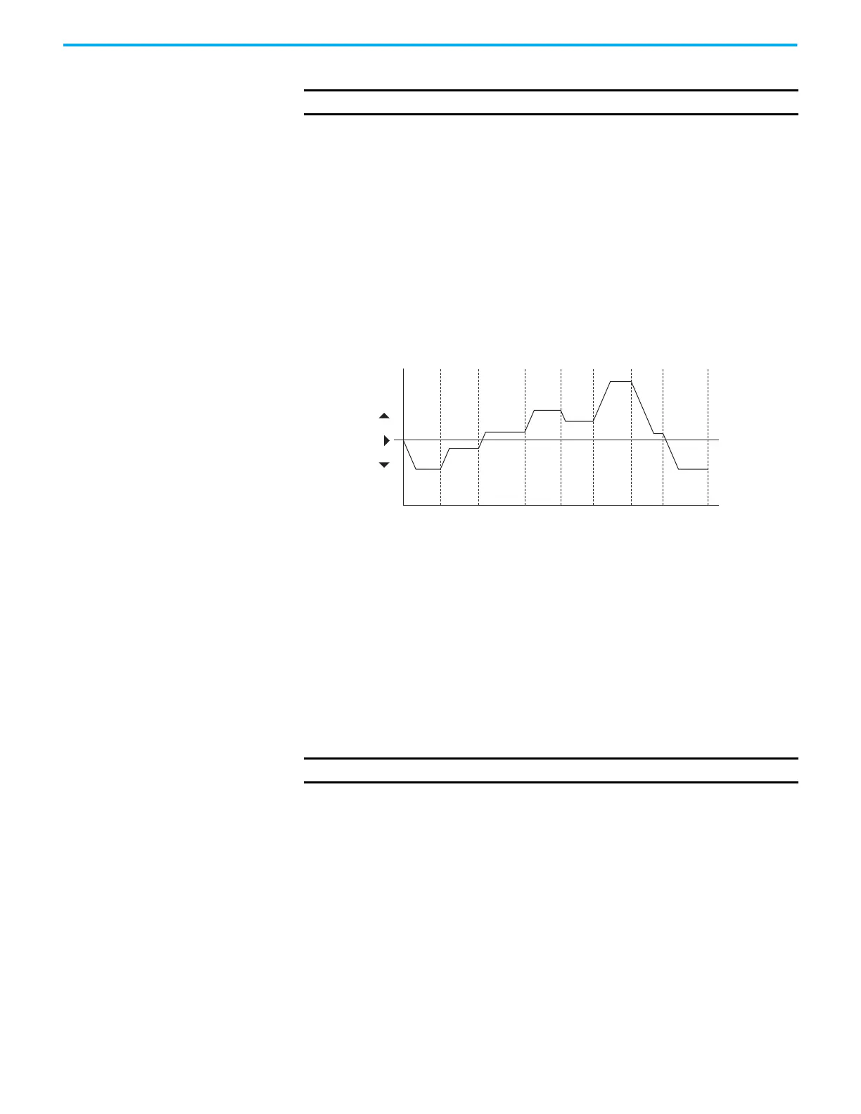
Using Timed Steps
Velocity StepLogic Sequence
• Sequence begins with a valid start command.
• A normal sequence begins with Step 0 and transition to the next step
when the corresponding StepLogic time has expired.
• Step 7 is followed by Step 0
• Sequence repeats until a stop is issued or a fault condition occurs.
Velocity StepLogic Using
Basic Logic Functions
Digital input and digital output parameters can be configured to use logic to
transition to the next step. Logic In 1 and Logic In 2 are defined by
programming parameters t062...t063, t065...t068 [DigIn TermBlk xx] to 24
“Logic In 1” or 25 “Logic In 2”.
Example
• Run at Step 0.
• Transition to Step 1 when Logic In 1 is true.
Logic senses the edge of Logic In 1 when it transitions from off to on.
Logic In 1 is not required to remain “on”.
• Transition to Step 2 when both Logic In 1 and Logic In 2 are true.
The drive senses the level of both Logic In 1 and Logic In 2 and transitions
to Step 2 when both are on.
IMPORTANT
This function is specific to PowerFlex 525 drives only.
Time
0
Forward
Reverse
Step 0 Step 1 Step 2 Step 3 Step 4 Step 5 Step 6 Step 7
IMPORTANT
This function is specific to PowerFlex 525 drives only.

 Loading...


