Rockwell Automation Publication 520-UM001K-EN-E - August 2021 213
Appendix D Velocity StepLogic, Basic Logic and Timer/Counter Functions
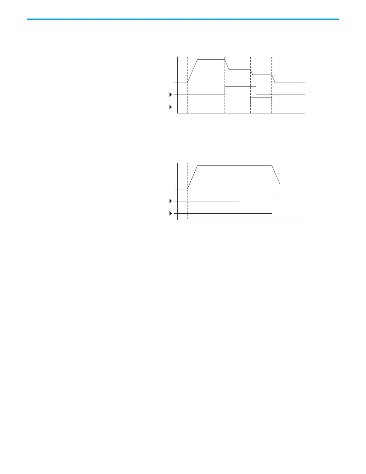
• Transition to Step 3 when Logic In 2 returns to a false or off state.
Inputs are not required to remain in the “on” condition except under the
logic conditions used for the transition from Step 2 to Step 3.
The step time value and the basic logic may be used together to satisfy machine
conditions. For instance, the step may need to run for a minimum time period
and then use the basic logic to trigger a transition to the next step.
Timer Function Digital inputs and outputs control the timer function and are configured with
parameters t062...t063, t065...t068 [DigIn TermBlk xx] set to 19 “Timer Start”
and 21 “Reset Timer”.
Digital outputs (relay and opto type) define a preset level and indicate when
the level is reached. Level parameters t077 [Relay Out1 Level], t082[Relay Out2
Level], t070 [Opto Out1 Level] and t073 [Opto Out2 Level] are used to set the
desired time in seconds.
Parameters t076 [Relay Out1 Sel], t081 [Relay Out2 Sel], t069 [Opto Out1 Sel]
and t072 [Opto Out2 Sel] are set to 25 “Timer Out” and causes the output to
change state when the preset level is reached.
Example
• Drive starts up and accelerates to 30 Hz.
• After 30 Hz has been maintained for 20 seconds, a 4…20 mA analog input
becomes the reference signal for speed control.
• The timer function is used to select a preset speed with a 20 second run
time that overrides the speed reference while the digital input is active.
• Parameters are set to the following options:
- P047 [Speed Reference1] = 6 “4-20mA Input”
- P049 [Speed Reference2] = 7 “Preset Freq”
- t062 [DigIn TermBlk 02] = 1 “Speed Ref 2”
- t063 [DigIn TermBlk 03] = 19 “Timer Start”
Time
Logic In 1
Logic In 2
Frequency
Start Step 0 Step 1 Step 2 Step 3
Time
Logic In 1
Logic In 2
Frequency
Start Step 0 Step 1

 Loading...


