Rockwell Automation Publication 520-UM001K-EN-E - August 2021 35
Chapter 1 Installation/Wiring
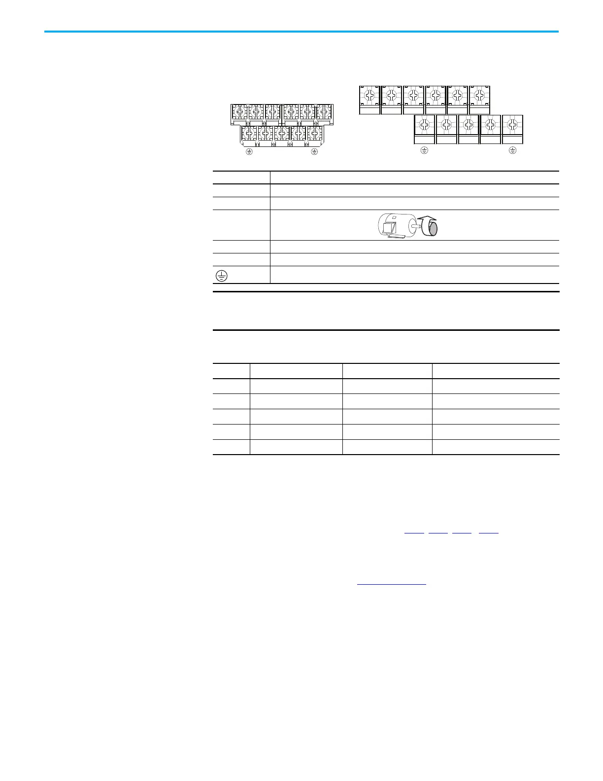
Power Terminal Block Power Terminal Block
Common Bus/Precharge
Notes
If drives are used with a disconnect switch to the common DC bus, then an
auxiliary contact on the disconnect must be connected to a digital input of the
drive. The corresponding input (parameter t062
, t063, t065...t068 [DigIn
TermBlk xx]) must be set to 30, “Precharge En” This provides the proper
precharge interlock, guarding against possible damage to the drive when
connected to a common DC bus. For more information, see Drives in Common
Bus Configurations, publication DRIVES-AT002
.
Terminal Description
R/L1, S/L2 1-Phase Input Line Voltage Connection
R/L1, S/L2, T/L3 3-Phase Input Line Voltage Connection
U/T1, V/T2, W/T3 Motor Phase Connection =
Switch any two motor leads to change
forward direction.
DC+, DC- DC Bus Connection (except for 110V 1-Phase)
BR+, BR- Dynamic Brake Resistor Connection
Safety Ground - PE
IMPORTANT
Terminal screws may become loose during shipment. Ensure that all
terminal screws are tightened to the recommended torque before applying
power to the drive.
Power Terminal Block Wire Specifications
Frame
Maximum Wire Size
(1)
(1) Maximum/minimum sizes that the terminal block will accept – these are not recommendations.
Minimum Wire Size
(1)
Torque
A
5.3 mm
2
(10 AWG) 0.8 mm
2
(18 AWG)
1.76...2.16 N•m (15.6...19.1 lb•in)
B
8.4 mm
2
(8 AWG) 2.1 mm
2
(14 AWG)
1.76...2.16 N•m (15.6...19.1 lb•in)
C
8.4 mm
2
(8 AWG) 2.1 mm
2
(14 AWG)
1.76...2.16 N•m (15.6...19.1 lb•in)
D
13.3 mm
2
(6 AWG) 5.3 mm
2
(10 AWG)
1.76...2.16 N•m (15.6...19.1 lb•in)
E
26.7 mm
2
(3 AWG) 8.4 mm
2
(8 AWG)
3.09...3.77 N•m (27.3...33.4 lb•in)
V/T2T/L3S/L2R/L1 U/T1 W/T3
V/T2T/L3S/L2R/L1 U/T1 W/T3
BR+
BR-
DC- DC+
BR+
BR-
DC-
DC+
Frame A, B, C & D Frame E

 Loading...


