Rockwell Automation Publication 520-UM001K-EN-E - August 2021 263
Appendix K
PowerFlex 525 Synchronous Reluctance Motor
Configuration
This chapter contains instructions and diagrams on configuring the
PowerFlex 525 drive for use with a Synchronous Reluctance Motor (SynRM)
control.
PowerFlex 525 drive is enhanced with SynRM control that allows an option to
pair with PF525 SynRM for energy efficiency and low effort in motor
maintenance.
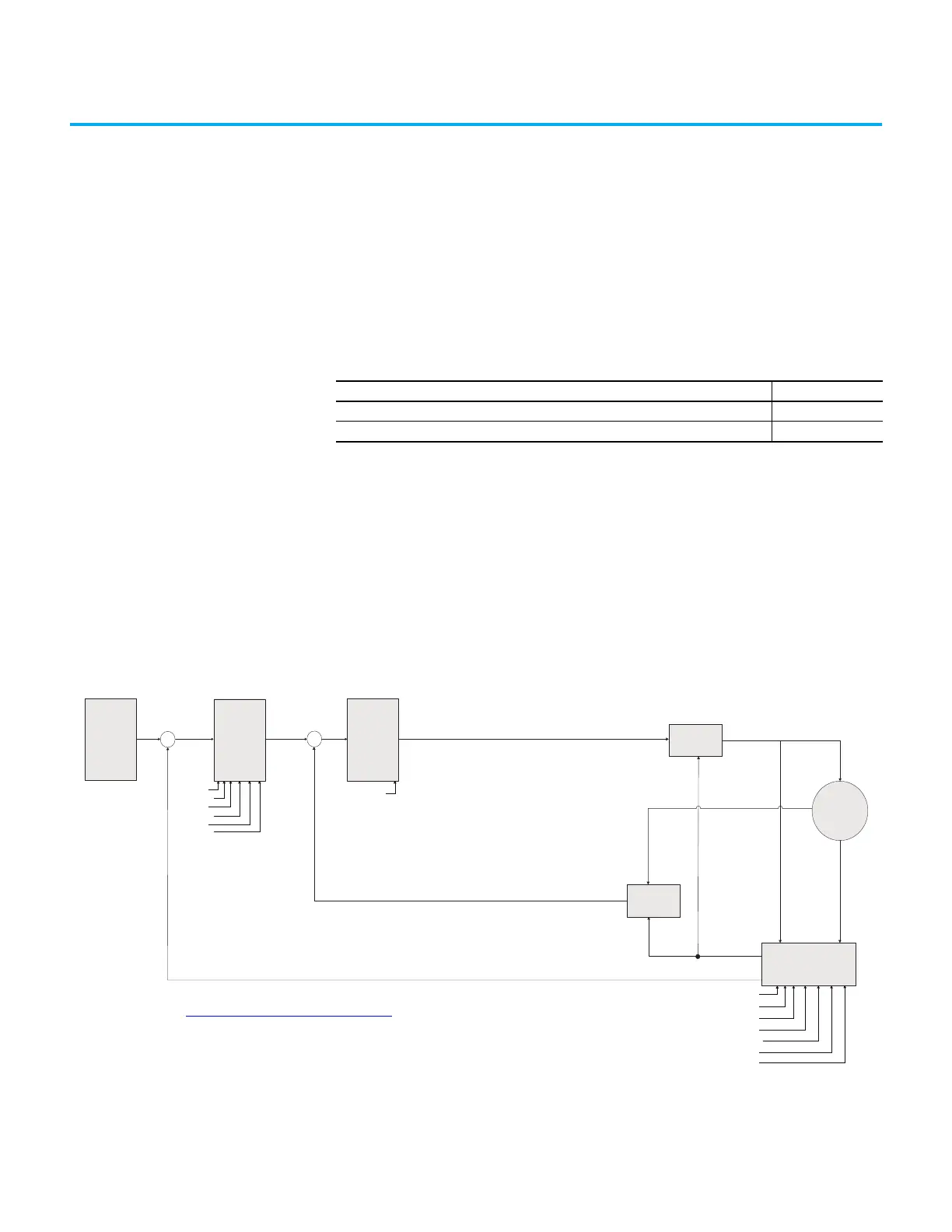
SynRM Structure Control Diagram
With PowerFlex 525 drive firmware revision 7.001, SynRM control can only be
configured manually using the keypad.
Topic Page
SynRM Structure 263
SynRM Control Configuration 264
Speed / Theta
estimated
+
-
+
-
Speed
Reference
(Keyboard,
2-wire,
digital ...)
P1 Regulator
Speed
cmd
Current
cmd
P1 Regulator
Speed Loop
Current Loop
Voltage
out
abc/dq
Current
feedback
dq/abc
Motor
A510 [Freq 1]
A511 [Freq 1 BW]
A512 [Freq 2]
A513 [Freq 2 BW]
A514 [Freq 3]
A515 [Freq 3 BW]
A590 [SYNRM SW Freq]
A591 [SYNRM Flux Cur]
A592 [SYNRM Freq1 Volt]
A593 [SYNRM Freq1 Kp]
A594 [SYNRM Freq1 Comp]
A595 [SYNRM Freq2 BW]
A596 [SYNRM Freq2 Kp]
A580 [Current Loop BW]
Theta
Speed
See Adjusting Speed Control Parameters on page 250 for more information on speed loop bandwidth
adjustment.

 Loading...


