Rockwell Automation Publication 7000-UM202H-EN-P - November 2023 65
Chapter 2 Power Component Definition and Maintenance
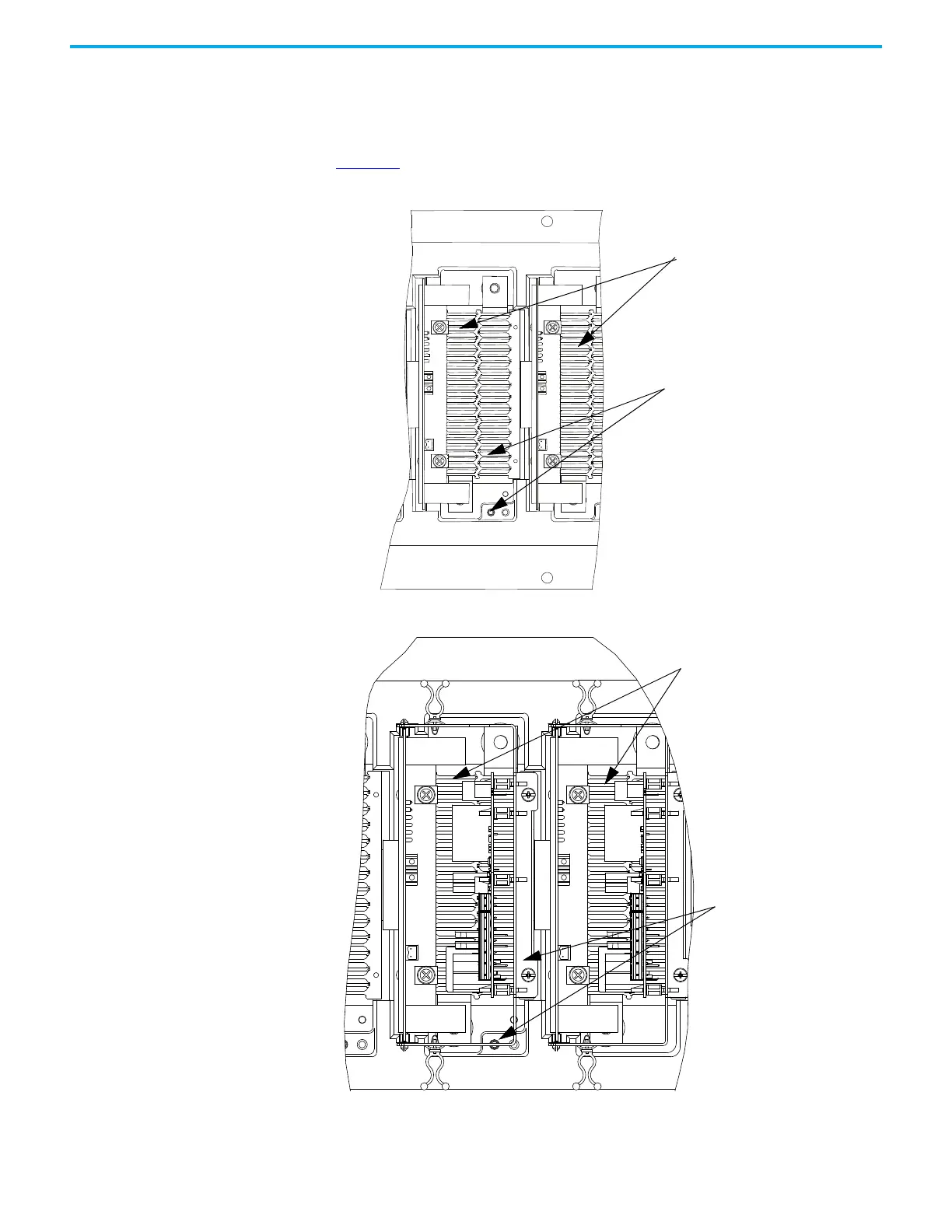
There is a test point inside the PowerCage module to measure the resistance of
the snubber resistor and capacitance of the snubber capacitor. The test point is
the electrical connection between the snubber resistor and snubber capacitor.
Place one probe of the multimeter on the test point and the other probe on the
appropriate heatsink to determine the value of the resistor or capacitor. See
Figure 54
.
Figure 54 - SGCT PowerCage Module
Figure 55 - Resistance Measurements SGCT PowerCage Module (with SPS Board Mounting Assembly)
Figure 56 - Resistance Measurements (Heatpipe Model)
Resistance value between two
heatsinks is sharing resistance
in parallel with anode-cathode
resistance
Resistance value between
heatsink and test point is
snubber resistance
Resistance value between two
heatsinks is sharing resistance
in parallel with anode-cathode
resistance
Resistance value
between heatsink and
test point is snubber
resistance

 Loading...


