98 Rockwell Automation Publication 7000-UM202H-EN-P - November 2023
Chapter 2 Power Component Definition and Maintenance
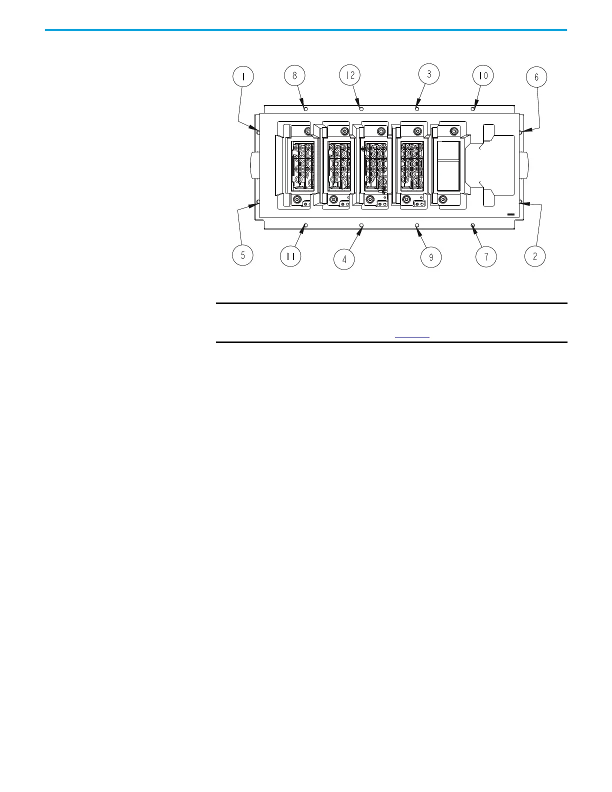
Figure 88 - Typical Torque Sequence
(a)
7. Replace interior assembly in the reverse order of removal.
(a) The PowerCage module is shown with switching components, heatsinks, and clamps removed for ease of lifting.
IMPORTANT A heatpipe PowerCage module does not have to be removed to access
the snubber resistors. The resistor cage can be removed within a
heatpipe PowerCage module (Figure 65).

 Loading...


