10
Reference Manual
00809-0100-4809, Rev DA
Section 2: Installation
September 2015
Installation
Note
Some recently-designed instrument manifolds have a single valve actuator, but cannot perform
all of the functions available on standard 5-valve units. Check with the manufacturer to verify
the functions that a particular manifold can perform. In place of a manifold, individual valves
may be arranged to provide the necessary isolation and equalization functions.
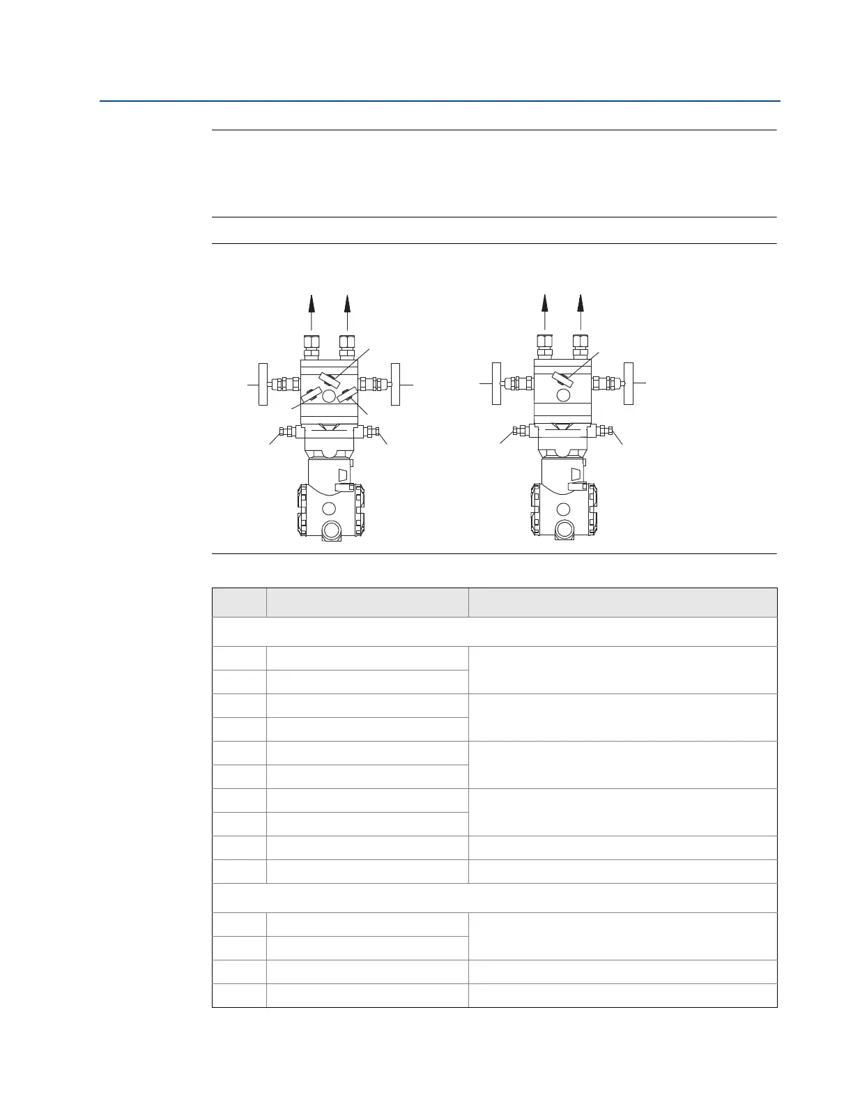
Figure 2-5. Valve Identification for 5-Valve and 3-Valve Manifolds
5-valve manifold 3-valve manifold
Table 2-1. Description of Impulse Valves and Components
Name Description Purpose
Manifold and impulse pipe valves
PH Primary Sensor – High Pressure
Isolates the flowmeter sensor from the impulse piping
system
PL Primary Sensor – Low Pressure
DVH Drain/Vent Valve – High Pressure
Drains (for gas service) or vents (for liquid or steam
service) the DP electronics chambers
DVL Drain/Vent Valve – Low Pressure
MH Manifold – High Pressure
Isolates high side or low side pressure from the
process.
ML Manifold – Low Pressure
MEH Manifold Equalizer – High Pressure
Allows high and low pressure side access to the vent
valve, or for isolating the process fluid
MEL Manifold Equalizer – Low Pressure
ME Manifold Equalizer Allows high and low side pressure to equalize
MV Manifold Vent Valve Vents process fluid
Components
1 Trans mitter
Reads Differential Pressure
Isolates and equalizes transmitter
2 Manifold
3 Vent Chambers Collects gases in liquid applications.
4 Condensate Chamber Collects condensate in gas applications.
To PH To PL
MV
ML
MEL
DVL
MH
MEH
DVH
2
1