22
Reference Manual
00809-0100-4809, Rev DA
Section 2: Installation
September 2015
Installation
2.6 Installation
This manual contains the horizontal and vertical installation procedures for the Pak-Lok,
Flanged, Flange-Lok, Threaded Flo-Tap, Flanged Flo-tap, and Main Steam Annubar sensor
models. For installation of the Compact Annubar Flowmeters, see Reference Manual (document
number 00809-0100-4810).
2.6.1 Pak-Lok Annubar sensor type (for 485 Annubar Flowmeters)
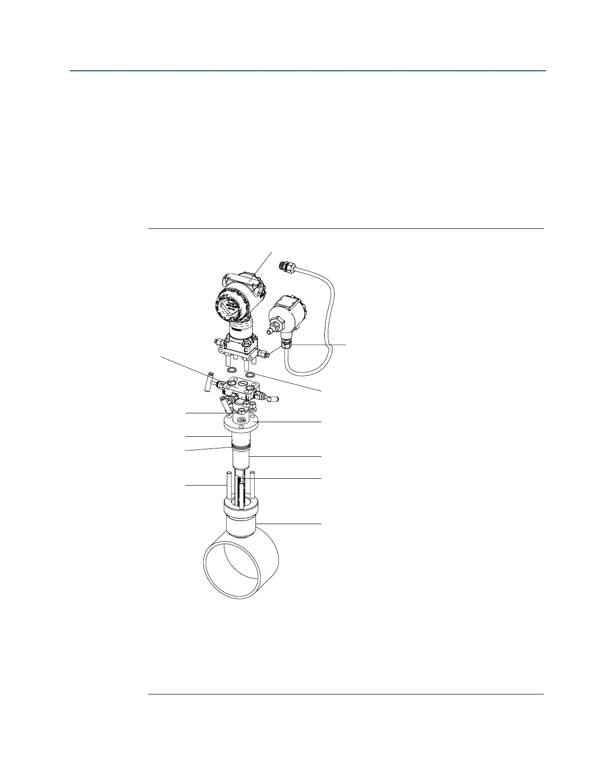
Figure 2-14 identifies the components of the Pak-Lok assembly.
Figure 2-14. Components
Transmitter and housing are shown for clarity purposes – only supplied if ordered.
A. Direct mount transmitter connection with valves
B. Nuts
C. Follower
D. Packing rings (3)
E. Studs
F. Transmitter
G. Coplanar flange with drain vents
H. O-rings (2)
I. Compression plate
J. Retaining ring
K. 485 Annubar sensor
L. Pak-Lok body