78
Reference Manual
00809-0100-4809, Rev DA
Section 4: Operation and Maintenance
September 2015
Operation and Maintenance
4.2.2 Electrical RTD check procedure
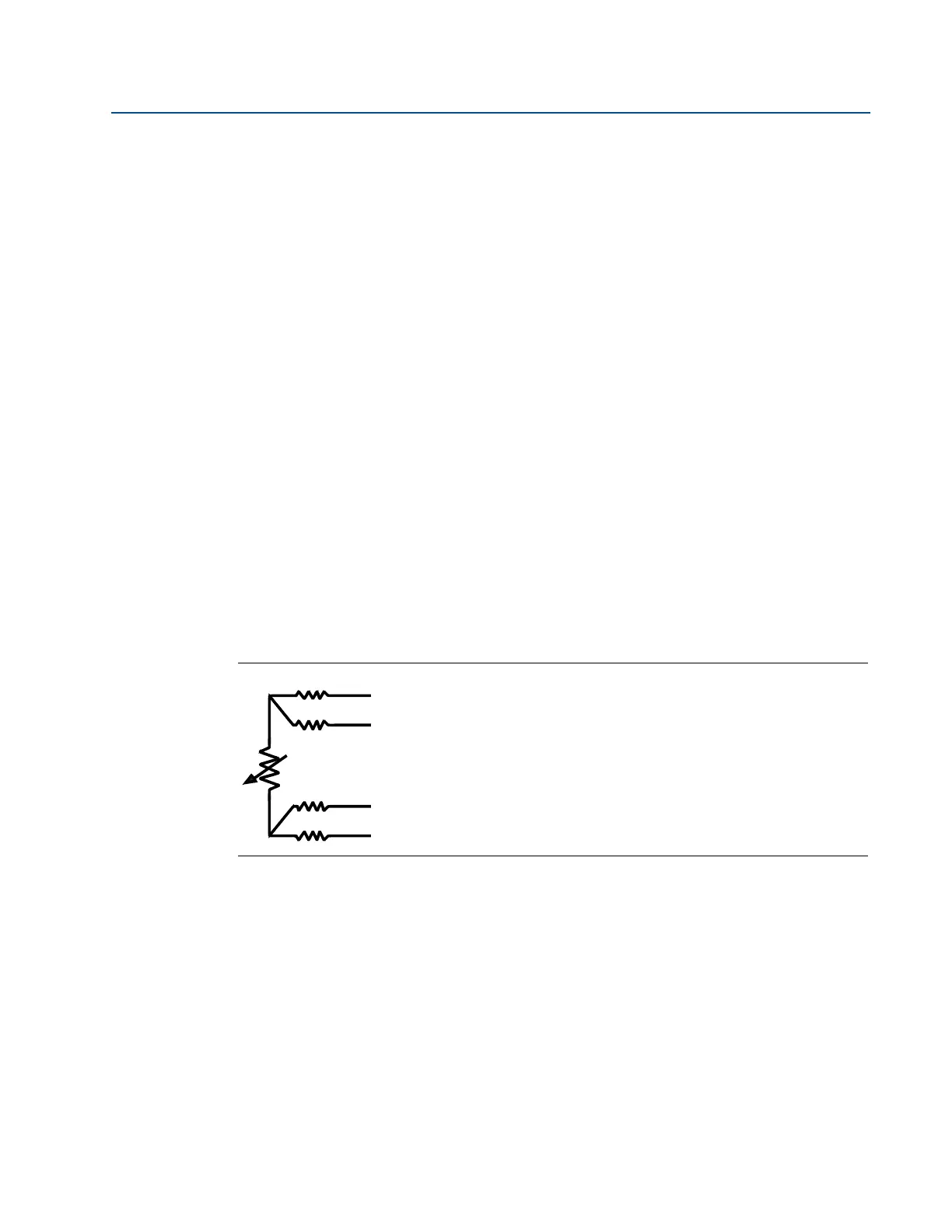
If the RTD is not functioning properly, perform the following checks to determine if the RTD is
failed. Figure 4-3 shows the schematic of a 4-wire RTD.
Continuity check
1. Using an Ohm meter or a Multimeter, check the resistance between each of the red and
white wires.
2. If the resistance measured represents the proper temperature, proceed to the
Grounding Check.
3. If the resistance measured does not represent the proper temperature or no resistance
is measured (i.e. Open circuit), the RTD is damaged and must be replaced.
Grounding check
1. Using an Ohm meter or a Multimeter, test for each wire of the RTD to the sheath for a
resistance value. If the RTD is installed in the Annubar sensor, test to the instrument
connections of Annubar sensor instead of the sheath of the RTD. All tests should
measure an infinite resistance (i.e. Open circuit) between the RTD wires and the sheath.
2. If all tests verify an open circuit, the RTD is functioning properly.
3. If any tests confirm a shorted wire to the RTD sheath, the RTD is damaged and must be
replaced.
Figure 4-3. Schematic of a Typical 4-Wire RTD