47
Reference Manual
00809-0100-4809, Rev DA
Section 2: Installation
September 2015
Installation
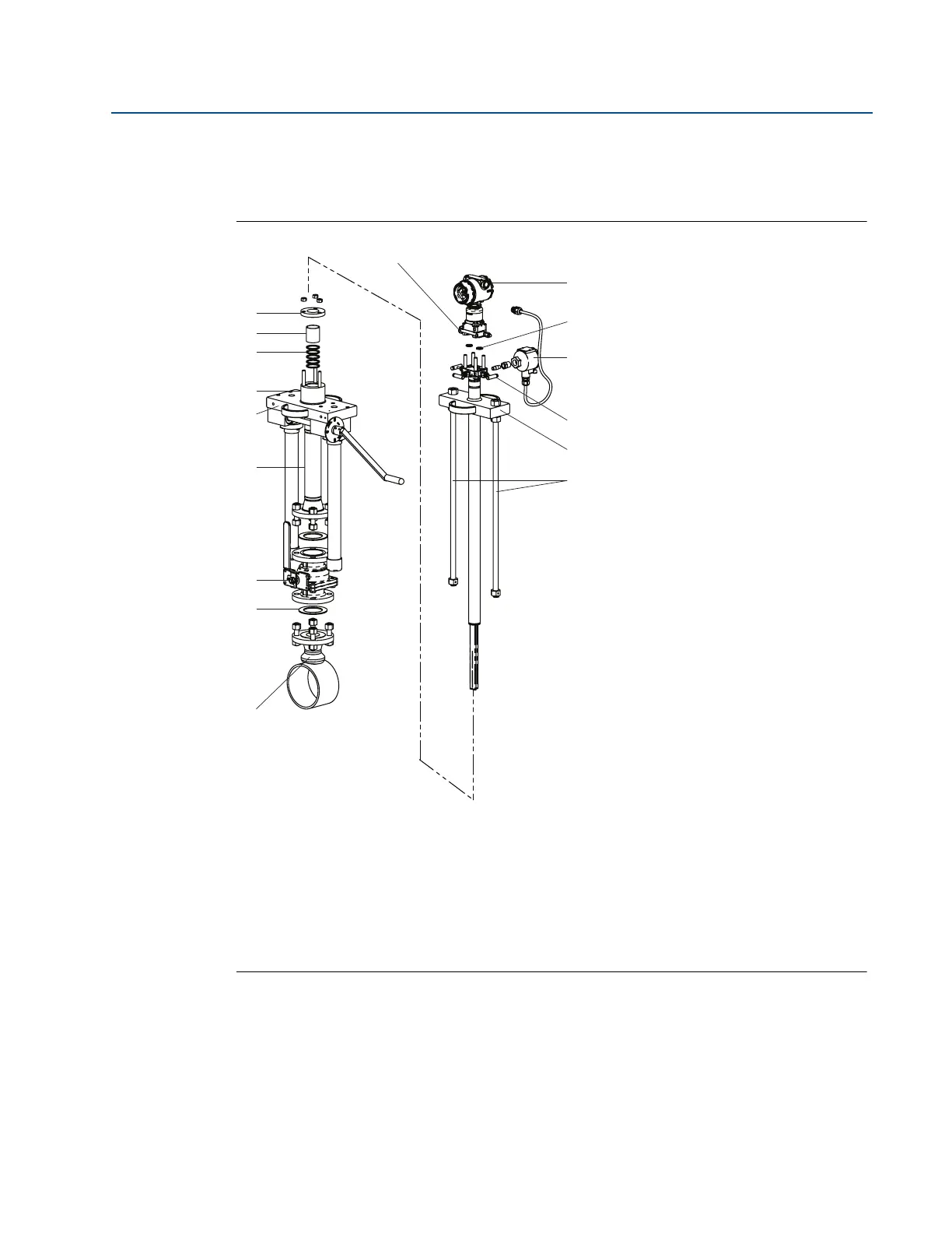
2.6.5 Flanged Flo-tap (for 485 and 585 Annubar Flowmeters)
Figure 2-32 identifies the components of the Flanged Flo-Tap assembly.
Figure 2-32. Components
Step 1: Determine the proper orientation
Refer to “Mounting” on page 8 for straight run requirements and orientation information.
Transmitter and housing are shown for clarity purposes – only supplied if ordered.
A. Coplanar flange with drain vents
B. Transmitter
C. O-rings (2)
D. Temperature sensor connection housing
E. Direct mount transmitter connection with valves
F. Head plate
G. Drive rods
H. Mounting flange assembly
I. Gasket
J. Isolation valve
K. Cage nipple
L. Support plate
M. Packing gland
N. Packing
O. Follower
P. Compression plate
A
B
C
D
E
F
G
H
I
J
K
L
N
O