34
Reference Manual
00809-0100-4809, Rev DA
Section 2: Installation
September 2015
Installation
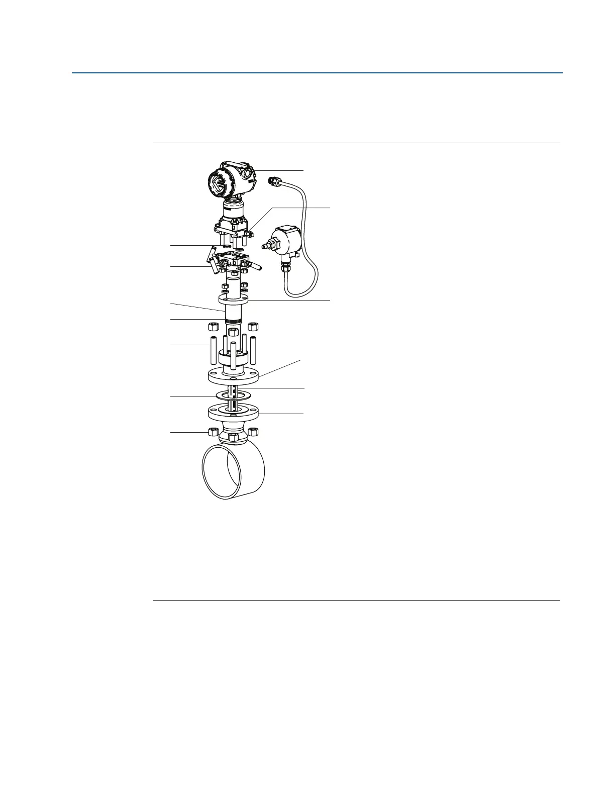
2.6.3 Flange-Lok model (for 485 Annubar Flowmeters)
Figure 2-22 identifies the components of the Flange-Lok assembly.
Figure 2-22. Components
Transmitter and housing are shown for clarity purposes – only supplied if ordered.
A. O-Rings (2)
B. Direct mount transmitter connection with valves
C. Follower
D. Packing rings (3)
E. Studs
F. Gasket
G. Transmitter
H. Coplanar flange with drain vents
I. Compression plate
J. Flange-Lok assembly
K. 485 Annubar sensor
L. Mounting flange assembly
M. Nuts
A
B
C
D
E
F
M
G
H
I
J
K
L