Reference Manual
00809-0100-4809, Rev DA
Appendix A: Specifications and Reference Data
September 2015
132
Specifications and Reference Data
A.6 3051CF specifications
A.6.1 Performance specifications
Performance assumptions include: measured pipe I.D, transmitter is trimmed for optimum flow accuracy, and performance is
dependent on application parameters.
A.6.2 Functional specifications
Range and sensor limits
Zero and span adjustment requirements (HART and low
power)
Zero and span values can be set anywhere within the range
limits stated in Table 9 and Table 10.
Span must be greater than or equal to the minimum span
stated in Table 9 and Table 10.
Service
Liquid, gas, and vapor applications
4–20 mA (output code A)
Output
Two-wire 4–20 mA, user-selectable for linear or square
root output. Digital process variable superimposed on
4–20 mA signal, available to any host that conforms to the
HART protocol.
Power supply
External power supply required. Standard transmitter
(4–20 mA) operates on 10.5 to 55 Vdc with no load.
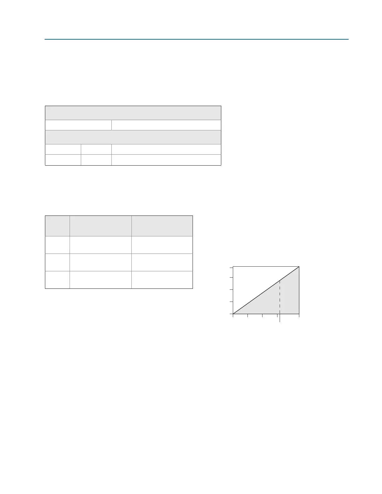
Load limitations
Maximum loop resistance is determined by the voltage
level of the external power supply, as described by:
F
OUNDATION Fieldbus (output code F) and PROFIBUS
(output code W)
Power supply
External power supply required; transmitters operate on
9.0 to 32.0 Vdc transmitter terminal voltage.
Current draw
17.5 mA for all configurations (including LCD display
option)
Table 8. Flow Performance - Flow Reference Accuracy
(1)
3051CFA Annubar Flowmeter
Ranges 2-3 ±1.80% of flow rate at 8:1 flow turndown
3051CFC_A Compact Annubar Flowmeter - Annubar option A
Ranges 2-3 Standard ±2.10% of flow rate at 8:1 flow turndown
Calibrated ±1.80% of flow rate at 8:1 flow turndown
1. Range 1 flowmeters may experience an additional uncertainty up to 0.9%. Consult
your Emerson Process Management Representative for exact specifications.
Table 9. 3051CF Range and Sensor Limits
Range
3051CF minimum
span
Range and sensor
limits
1
0.5 inH
2
O
(1,2 mbar)
0 to 25 inH
2
O
(62,3 mbar)
2
2.5 inH
2
O
(6,2 mbar)
0 to 250 inH
2
O
(0,63 bar)
3
10 inH
2
O
(24,9 mbar)
0 to 1000 inH
2
O
(2,49 bar)
Max. Loop Resistance = 43.5 ⫻(Power Supply Voltage – 10.5)
Communication requires a minimum loop resistance of 250 .
1. For CSA approval, power supply must not exceed 42.4 V.
1935
1500
1000
500
0
10.5 20 30 40
42.4
55
Load (Ohms)
Voltage (Vdc)
Operating
region
(1)