55
Reference Manual
00809-0100-4809, Rev DA
Section 2: Installation
September 2015
Installation
2.6.6 Main steam line (for 585 Annubar Flowmeters)
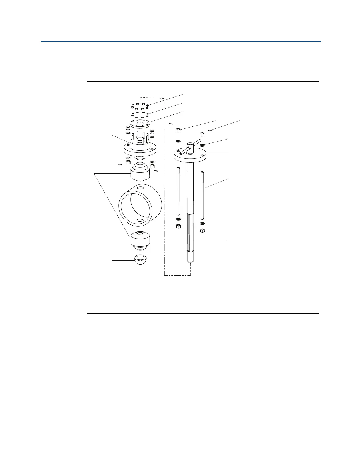
Figure 2-37 identifies the components of the Main Steam Annubar sensor assembly.
Figure 2-37. Components
Step 1: Determine the proper orientation
Refer to “Mounting” on page 8 for straight run requirements and orientation information.
Step 2: Drill mounting hole into pipe
1. De-pressurize and drain the pipe.
2. At the predetermined position, drill the hole into the pipe wall in accordance with the
instructions provided by the drilling machine manufacturer. Drill 2.5-in. (64 mm) hole.
Drill hole has a tolerance of +
1
/16-in. or -0 in. (1,6 mm or -0 mm).
A. Packing gland
B. Weldolet
C. Opposite side support cap
D. Packing gland nuts
E. Packing gland washers
F. Packing Gland Cover
G. Locking nuts
H. Roll pins
I. Locking washers
J. Remote mount instrument connections
K. Locking rods
L. 585 sensor