49
Reference Manual
00809-0100-4809, Rev DA
Section 2: Installation
September 2015
Installation
2. Place four
1
/4-in. (6-mm) tack welds at 90° increments. Check alignment of the
mounting both parallel and perpendicular to the axis of flow.
3. If the mounting alignment is within tolerances, finish weld per local codes. If outside of
tolerances, make adjustments prior to making the finish weld.
4. To avoid serious burns, allow the mounting hardware to cool before continuing.
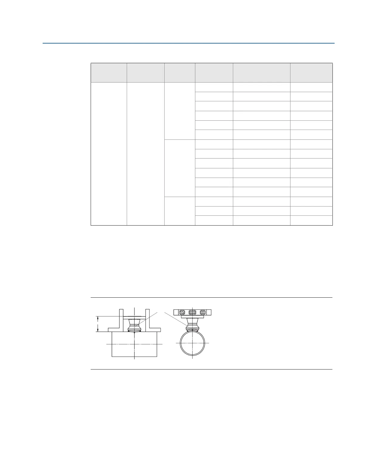
Figure 2-33. Alignment
A. Tack weld
Step 3: Install the isolation valve
1. Position the isolation valve onto the mounting flange. Ensure the valve stem is
positioned so that when the Flo-Tap is installed, the insertion rods will straddle the pipe
and the valve handle will be centered between the rods (see Figure 2-34).
3 44
A
1 3.0-in. 150# RF 4.63 (117.6)
3 3.0-in. 300# RF 5.00 (127.0)
6 3.0-in. 600# RF 5.38 (136.7)
N 4.0-in. 900# RF 8.19 (208.0)
F 4.0-in. 1500# RF 8.56 (217.4)
T 4.0-in. 2500# RF 11.19 (284.2)
R
1 3.0-in. 150# RTJ 4.81 (122.2)
3 3.0-in. 300# RTJ 5.25 (133.4)
6 3.0-in. 600# RTJ 5.44 (138.2)
N 4.0-in. 900# RTJ 8.25 (209.6)
F 4.0-in. 1500# RTJ 8.63 (219.2)
T 4.0-in. 2500# RTJ 11.38 (289.1)
D
1 DN80 PN16 RF 3.85 (97.8)
3 DN80 PN40 RF 4.16 (105.7)
6 DN80 PN100 RF 4.95 (125.7)
1. Tolerances for the ODF dimension above a 10-in. (254 mm) line size is ±0.060-in. (1,6 mm). Below 10-in. (254 mm) line size is
±0.030-in. (0,8 mm).
Table 2-10. 485 and 585 Flange Sizes and ODF per Sensor Size
485 Sensor
size
585 Sensor
size
Flange
type
Pressure
class
Flange size/
rating/type
ODF in.
(mm)
(1)
AODF
 Loading...


