58
Reference Manual
00809-0100-4809, Rev DA
Section 2: Installation
September 2015
Installation
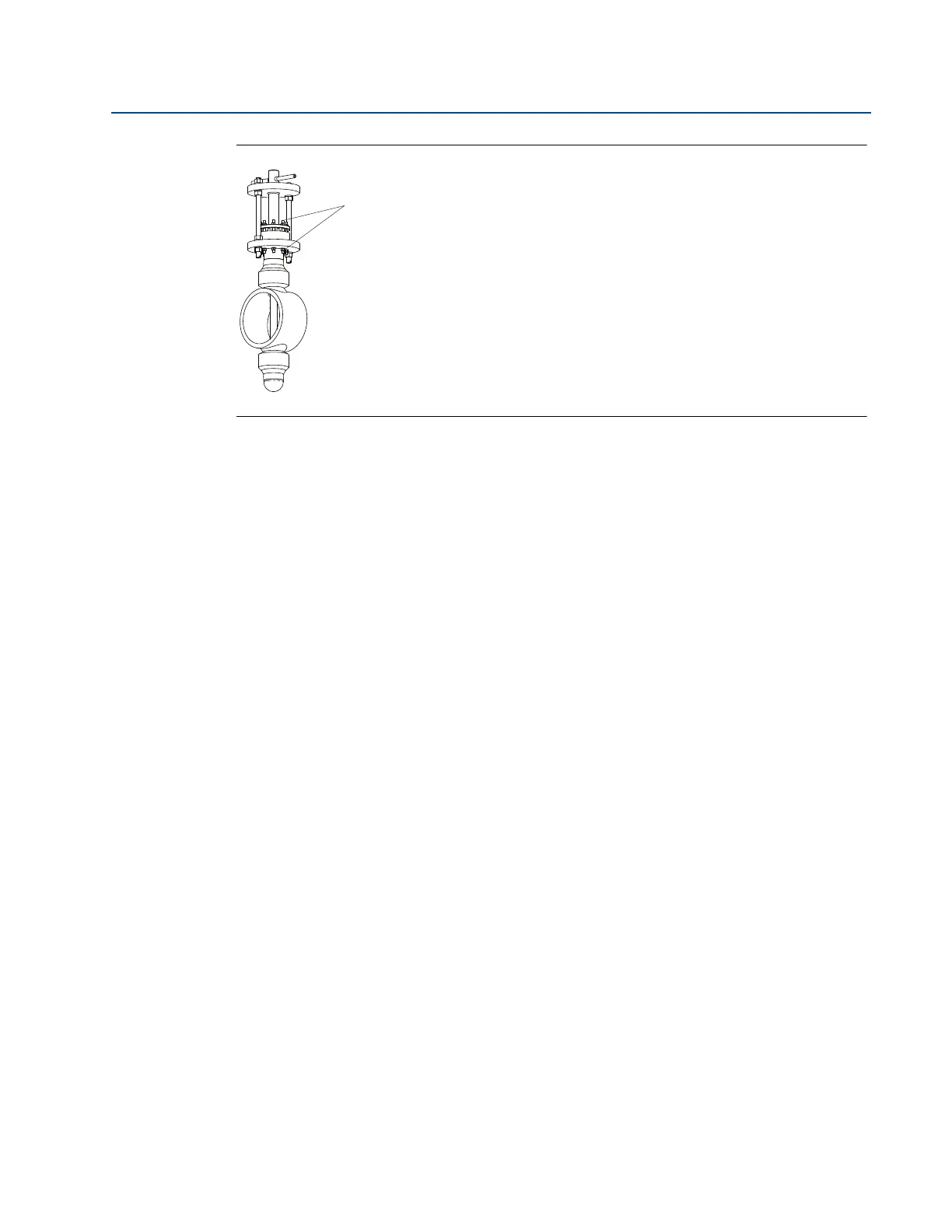
Figure 2-38. Tighten The Packing Gland Nuts
A. Packing gland nuts
Step 5: Mount the transmitter
Impulse piping that runs horizontally must slope downward at least one inch per foot
(83 mm/m).
Impulse piping should have a minimum length of 1-ft. (0.3048 m) for every 100 °F
(38 °C) temperature increase over 250 °F (121 °C).
a. Impulse piping must be non-insulated to reduce fluid temperature.
b. Any threaded connections should be checked after the system reaches the intended
temperature because connections may come loose with contraction and expansion
caused by temperature change.
Outdoor installations may require insulation and heat tracing to prevent freezing.
When impulse piping is longer than 6-ft. (1.8 m) the high and low impulse lines must be
positioned together to maintain equal temperature. They must be supported to
prevent sagging and vibration.
Impulse lines should be positioned in protected areas or against walls or ceilings. Use
appropriate pipe sealing compound rated for the service temperature on all threaded
connections. Do not place the impulse piping near high temperature piping or
equipment.
a. An instrument manifold is recommended for all installations. Manifolds allow an
operator to equalize the pressures prior to zeroing and isolates the process fluid
from the transmitter.
b. Use only valves and fittings rated for the design pressure and temperature (in some
cases the primary instrument valve may be supplied by Emerson Process
Management with the Annubar sensor).
c. Use a pipe thread sealant compound that is rated for use at the service temperature
and pressure for all valves and fittings.
d. Verify that all connections are tight and that all instrument valves are fully closed.
e. Verify that the sensor probe is properly oriented as per the submitted outline
drawings.
f. The piping used to connect the sensor probe and transmitter must be rated for
continuous operation at the pipeline-designed pressure and temperature. A
minimum of one-half inch (
1
/2-in., 12 mm) O.D. stainless steel tubing with a wall
thickness of at least
1
/16-in. (1,6 mm) is recommended.