BRP-Rotax
MAINTENANCE MANUAL LINE
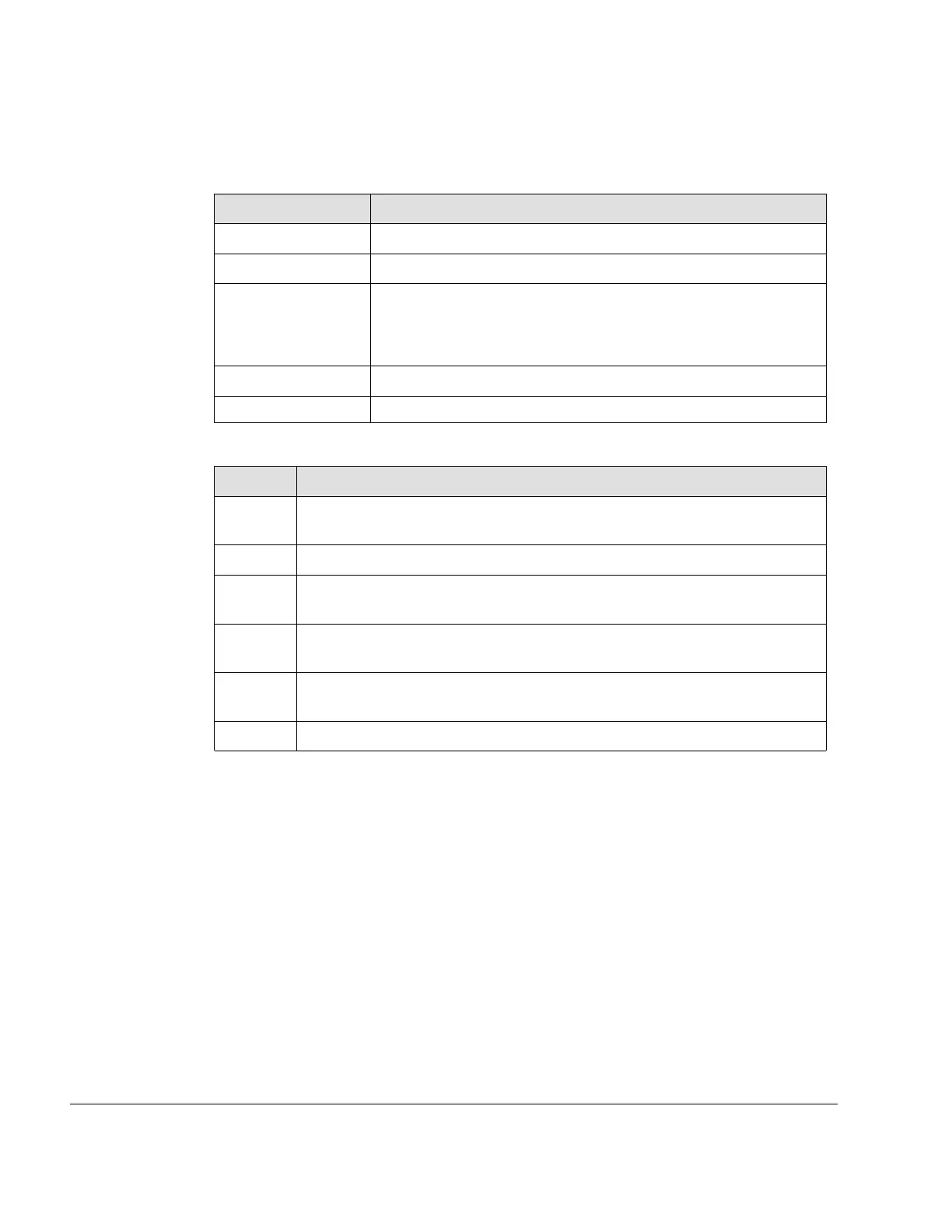
Special tools To measure the differential pressure the following special tools and equipment are
necessary.
Part number Description
n.a.
Compressed air approx. 6 bar (80 psi).
n.a
2 pressure gauges.
n.a
Orifice jet*, of 1 mm (0.04 in) inner diameter and 3 mm (0.12 in)
length. * or equivalent e.g. orifice diameter 0.040 in., long 0.0250
in., 60° degree approach angle according to AC43.13, latest
issue.
n.a
Adapter to spark plug thread.
n.a
Connect line.
Instruction Testing is carried out using the differential pressure test procedure.
Step
Procedure
1 Operate the engine until the temperatures have stabilized for a period of 5
min (engine oil temperature between 50 to 70 °C (122 - 160 °F).
2
Starting with cylinder head 1 move piston to TDC position.
3 Remove the upper spark plugs. Prevent dirt or other foreigner particles from
penetrating the engine (A).
4
Screw adaptor (1) into the spark plug thread and connect up the two pres-
sure gauges (2) with the orifice jet (3) between them (B).
5
Now put constant pressure, between 5.5-6 bar (80 psi) on the line and take
readings at pressure gauge (C)..
6 Repeat this proceeding at all 4 cylinder heads.
Value The maximum permissible pressure drop is 25 %, e.g. from 6 to 4.5 bar (80 psi to 65 psi)
(D).
If the pressure loss is less than 25% then the valve seats and piston rings are working
properly. The spark plug has to be installed according to Chapter 12–20–00 section Instal-
lation of spark plugs.
If the value is over 25% inspection, repair or overhaul must be carried out in accordance
with the BRP-Rotax instructions for continued airworthiness.
• Detailed inspection of affected engine components.
12–20–00
Page 8
September 01/2018
Effectivity: 912 i Series
Edition 2/Rev. 0

 Loading...


