EasyManuals Logo

Rotax 912 i series Service Manual

Rotax 912 i series
168 pages
To Next Page IconTo Next Page
To Previous Page IconTo Previous Page
Page #71 background imageLoading...
Page #71 background image
BRP-Rotax
MAINTENANCE MANUAL LINE
REMOVAL OF THE DRIVE GEAR
ATTENTION
The large and small gears are considered the same part with the same part num-
ber and same serial number. They must not be mixed up with other gear sets.
Step
Procedure
1 Heat the hex. nut M30x1.5 with the hot air gun (100–120 °C (212–248 °
F)).
2
Turn clockwise left hand threads to loosen hex. nut M30x1.5 with socket
wrench SW 41 part no. 877445.
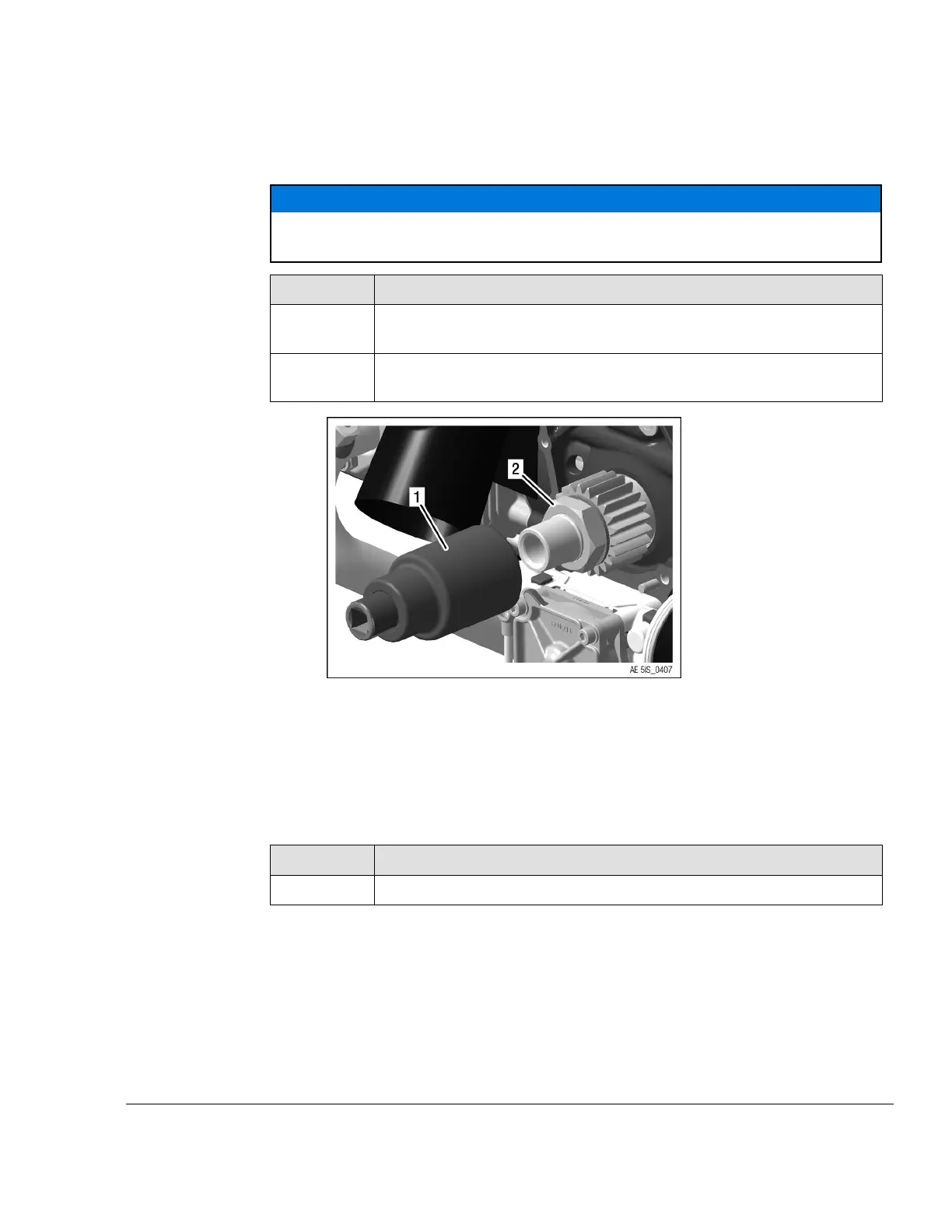
Figure 5.4
1
Socket wrench SW 41 part no. 877445
2 Hex. nut M30x1.5
NOTE
The hex. nut has a left handed thread!
Step
Procedure
3
Remove the drive gear and the friction washer from the crankshaft.
NOTE
If necessary, carefully lever off the drive gear with 2 screwdrivers.
NOTE
The gear set (large and small drive gear) are part of the gearbox assy. and both
must be included if sending gearbox out for inspection or overhaul.
Effectivity: 912 i Series
Edition 2/Rev. 0
05–50–00
Page 5
September 01/2018

Table of Contents

Other manuals for Rotax 912 i series

Questions and Answers:

Question and Answer IconNeed help?

Do you have a question about the Rotax 912 i series and is the answer not in the manual?

Rotax 912 i series Specifications

General IconGeneral
Number of Cylinders4
Max Power100 hp (73.5 kW)
Max Power Output RPM5800 rpm
Ignition SystemDual electronic ignition
Oil SystemDry sump, forced lubrication with separate oil tank
Reduction Gear Ratio2.43:1
TBO2000 hours
Engine Type4-stroke, horizontally opposed
Displacement1352 cm³
Bore x Stroke84 mm x 61 mm
Max Torque128 Nm
Fuel TypeAvgas 100LL or unleaded automotive gasoline
Fuel SystemElectronic fuel injection
Cooling SystemLiquid/air-cooled

Related product manuals